Mesh Data explained: What’s in Your Mesh and How Shaders Use It

Tutorial / 09 September 2025

This article is designed as a practical and readable guide to every vertex attribute in Unity. Particularly, what they are, how they’re stored in memory, how shaders access them, and how you can add your own for fast, efficient vertex operations.

We’ll be working in Unity 6.0+ with URP 17+, using them as both the primer and the playground.

My overall intention is that, by the end, you’ll have a clear understanding of what lives inside a mesh, how that data makes its way into your shaders, which “places” are best for custom attributes, and how to deform geometry at the vertex stage without stalls, seams, or unexpected behavior.

Let’s dive in!

---

Contents:

  1. From DCC (authoring application) to Vertex Shader - The Big Picture
  2. Vertex Attributes. What They Are and Why They Matter
    • A typical GPU-friendly data layout
  3. Detailed attributes breakdown
    • Position
      • Example: per-vertex position transforms
    • Normal
      • Example: normals processing and transforms
    • Tangent
      • Example: TBN matrix build-up
    • UV Sets
      • Standard UV Sets
      • Efficient Usage: half vs float
      • Example: Base and Lightmap UVs
      • Custom Data in UV Channels
      • Example: uv2 channel usage
      • Conventions you might find useful in your pipelines
    • Vertex Color
      • Sample channels usage scenario
      • Example: Sampling Specific Vertex Color Data
      • Example: Using Vertex Colors Instead of Textures
    • Skin weights and indices
      • Recommended practices
    • Blend Shapes
      • Example: Blend Shapes deltas sampling within shader
  4. Data Packing & Precision
    • Why precision matters
    • Where half precision shines
      • Example: data processing and demote (type cast)
      • More samples of using half precision
    • Where you should stick with float
    • Per-Platform notes
  5. Where to Put Custom Data
    • Additional vertex streams
    • Structured/GraphicsBuffer
    • GPU Instancing / SRP Batcher
      • Example: GPU Instancing setup
      • Example: SRP Batcher support implementation
  6. Vertex Deformation & Transforms within the Shader
    • Example: Vertex deformation pattern 
  7. Mesh attributes used by Renderer components in Unity

--- 

From DCC (authoring application) to Vertex Shader - The Big Picture

Think of a mesh as a spreadsheet the GPU can read very quickly. Each row is a vertex; each column is an attribute. A second file of tiny integers (your index buffer) tells the GPU which three rows make a triangle. Submeshes are just named slices through that index file. With this slice, different triangles can use different materials.

Processing a mesh involves several steps: 

  • Authoring App (Houdini, Blender, Maya, etc.). Artists define geometry, materials, and extra data (UVs, vertex colors, skin weights).
  • Mesh Data. A mesh is a structured collection of vertex and index buffers. Each vertex can store multiple attributes: 
    • position, 
    • normal, 
    • tangent, 
    • UV sets, 
    • vertex color, 
    • skin weights and indices, 
    • blend shapes. 

These attributes define the geometry and visual behavior of the mesh, and later determine how it can be manipulated or deformed within shaders. 

  • Engine Import. CPU prepares mesh data, packs attributes efficiently, and sets up additional streams if needed. The engine reads the file and builds its internal mesh representation, optimizing data for the render pipeline (e.g., compression and precision adjustments).
  • GPU Buffers. Vertex attributes are uploaded into GPU memory.
  • Vertex Shader. The shader consumes attributes, transforms geometry, and can apply deformations using both built-in and custom data

When a draw happens, an engine streams one row (the current vertex) into your vertex function. The function transforms it from object space to clip space and sends only chosen values forward as varyings for the fragment stage. Be mindful of the varying amounts. If you allocate too much, you could end up overspending on certain platforms. This is why mesh layout and packing matter even if your math is simple. 

The cost of moving data often dwarfs the cost of a few extra ALU instructions.

--- 

Vertex Attributes. What They Are and Why They Matter

A typical GPU-friendly data layout

Before we unpack each attribute, it helps to have a mental target. The layout below prioritizes bandwidth and cache friendliness without sacrificing the data shaders need for lighting and deforms. It also maps cleanly to Unity/URP semantics.

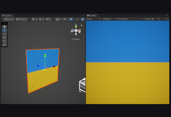
Unity attributes layout for a default quad looks like that:

position              : float32 x 3       // 12 bytes (3 × 4)
normal       : float32 x 3    //  12 bytes (3 × 4)
tangent (+sign)       : float32 x 4 //  16 bytes (4 x 4)
uv0                   : float32 x 2         //  8 bytes (4 x 2)
uv1 (lightmap)        : float32 x 2 //  8 bytes (4 x 2)
----------------------------------------------------
Total per-vertex                       56 bytes


To summarize, positions stay full-precision, normal and tangent vectors are compact but stable. UVs/colors use half/unorm where range is small.

And if skinned meshes data is present:

+ boneIndices : uint32 x 4 // 16 bytes (4 x 4)
+ boneWeights         : float32 x 4 //  16 bytes (4 x 4)
----------------------------------------------------
Total per-vertex 88 bytes


Important note:

If you leave Unity’s defaults, bone weights may arrive as float4 (16 bytes). Switching to unorm8x4 plus normalization in the shader saves 12 bytes/vertex with no visible loss for typical rigs.


But how this data is represented within Unity shader? Let's take a look:

struct Attributes
{
    float3 positionOS : POSITION;
    float3 normalOS   : NORMAL; // Packed snorm 10:10:10:2 is expanded to float3 by Unity; you can effectively decode it yourself
    float4 tangentOS  : TANGENT;   // xyz = tangent, w = bitangent sign (±1)
    half2  uv0        : TEXCOORD0; // base textures
    half2  uv1        : TEXCOORD1; // lightmap/GI
    half4  color      : COLOR;     // unorm8x4 -> 0..1
    uint4  boneIndex  : BLENDINDICES0; // skinned only (u8x4)
    half4  boneWeight : BLENDWEIGHT0;  // skinned only (unorm8x4 -> 0..1)
};

---

Detailed attributes breakdown

Position 

Represents the location of the vertex. Positions are stored in object space: coordinates relative to the mesh’s local origin. Most pipelines keep them as three 32-bit floats, though it’s common to quantize to 16-bit plus a scale/offset when building custom formats.

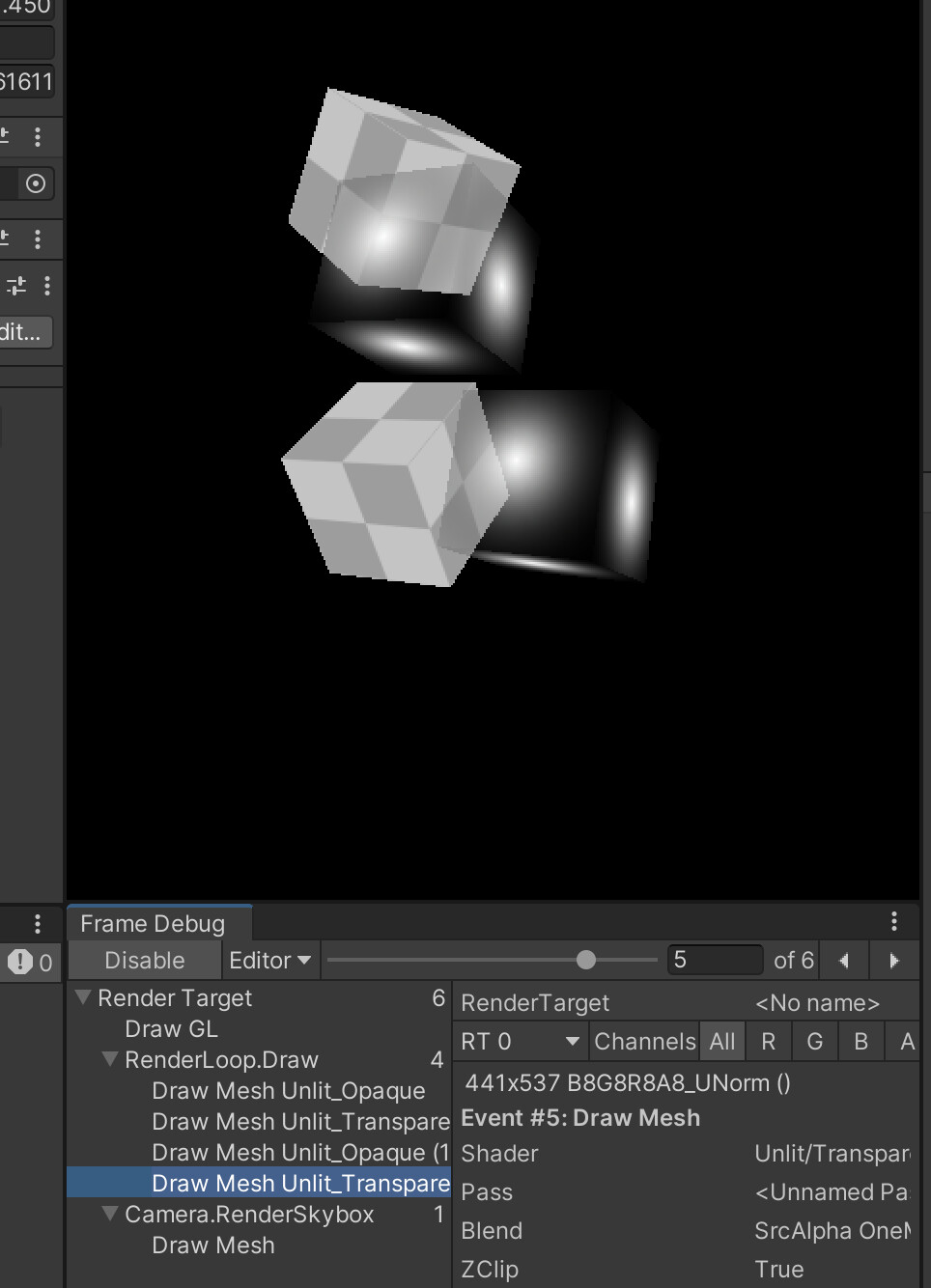
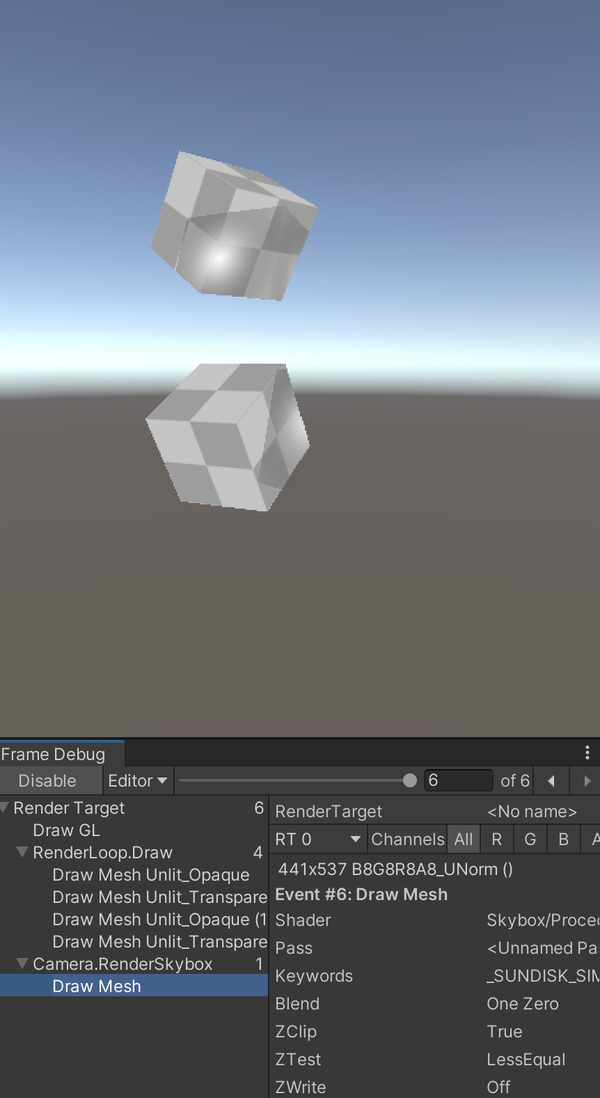
In the vertex shader, positions are usually deformed in object space, then transformed to world and clip space. If you bend a mesh, make sure normals and tangents follow the deformation; otherwise, lighting will appear incorrect (“sliding highlights”).

Example: per-vertex position transforms

float3 posOS = IN.positionOS;    // object space
float3 posWS = TransformObjectToWorld(posOS); // world space
OUT.positionCS = TransformWorldToHClip(posWS); // homogeneous clip space


Important note:

Saying a vertex is in “clip space” can be a bit misleading. After the vertex shader applies the projection matrix, the coordinates are actually in homogeneous clip space. It`s a 4D space (x, y, z, w) before the GPU performs the perspective divide. Only after dividing by w do we get Normalized Device Coordinates (NDC), which are the 3D coordinates the GPU uses for rasterization.


Normal

Represents the direction the vertex/surface faces. It`s a unit vector perpendicular to the surface, used by lighting models (e.g., Lambert, GGX) to determine how bright a point should appear.

Common storage options:

  • Three floats: simple but bandwidth-heavy.
  • Octahedral encoding: 2 components (8 or 16 bits) reconstruct a 3D unit vector.
  • 10:10:10:2 packed snorm: packs a 3D vector plus sign into a single 32-bit value.


Example: normals processing and transforms

float3 normalOS = normalize(IN.normalOS); // normalized surface (object-space) normal
float3 normalWS = TransformObjectToWorldNormal(nOS); // transformed to world-space normals data


Important note:

Keep encoding consistent across passes and platforms, and renormalize after any transform or blending


Tangent

Represents how to orient a normal map. Normals alone aren’t enough to interpret a tangent-space normal map. To construct the TBN (Tangent, Bitangent, Normal) basis, you also need a tangent and bitangent orientation.


Example: TBN matrix build-up

float3x3 BuildTBN(float3 normal, float4 tangent)
{
    float3 N = normalize(normal);                    // unit‑length normal
    float3 T = normalize(tangent.xyz);               // unit‑length tangent
    float3 B = normalize(cross(N, T)) * tangent.w;   // unit‑length bitangent (handedness +1 or -1)
    return float3x3(T, B, N);                       // column‑major matrix: T, B, N
}


UV sets

UV sets are 2D coordinates used by shaders to sample textures. They are also excellent candidates for storing small per-vertex custom data

Standard UV Sets

Most meshes include multiple UV sets:

  • uv0 - drives base color, normal maps, and other standard textures,
  • uv1 - typically reserved for lightmaps and baked GI. Keep this set clean: non-overlapping islands and proper padding are essential because lighting expects well-behaved UVs. 
  • uv2+ - optional extra UVs for decals, detail layers, triplanar weights, or per-vertex payloads like weights, masks, or scalars.

On the shader side UV arrive as float2, but it’s often safe to use them as half2 once you’re inside the shader. Many teams also quantize UVs to 16-bit at build time without visible loss, especially for non-hero assets.


Important note:

Always document repurposed UV channels: which component stores what, their ranges (0-1, signed, scaled), and which shader passes use them. This prevents hard-to-debug issues, especially in shadow or lightmap passes.

Efficient Usage: half vs float

  • UVs data precision is float2 by default.
  • Safe to demote (type cast) to half2: If you don’t perform heavy screen-space derivatives or large procedural calculations, converting to half2 halves the bandwidth cost with negligible visual difference.
  • Keep float2: When UVs are used for custom filtering, screen-space derivatives or procedural coordinates where small quantization errors become noticeable.

Example: Base and Lightmap UVs

struct Attributes
{
    float2 uv0 : TEXCOORD0;   // Base textures
    float2 uv1 : TEXCOORD1;   // Lightmaps / baked GI
};

struct Varyings
{
    float4 positionCS : SV_POSITION;
    half2  uvBase     : TEXCOORD0;   // Demoted to half2 for bandwidth
    half2  uvLight    : TEXCOORD1;  // Lightmaps / baked GI
};

Varyings Vert(Attributes IN)
{
    Varyings OUT;

    // Transform, etc.
    ...

    OUT.uvBase  = (half2)IN.uv0;     
    OUT.uvLight = (half2)IN.uv1;     

    return OUT;
}

half4 Frag(Varyings IN) : SV_Target
{
    // Sample base texture
    half2 uv = IN.uvBase;
    float4 col_base = SAMPLE_TEXTURE2D(_BaseMap, sampler_BaseMap, uv);

    // Sample lightmap
    float2 lightmapUV = IN.uvLight * unity_LightmapST.xy + unity_LightmapST.zw;
    float3 bakedLight = SAMPLE_TEXTURE2D(unity_Lightmap, samplerunity_Lightmap, lightmapUV).rgb;

    // Combine lighting
    return albedo;
}


Custom Data in UV Channels

Extra UV sets (uv2+) can carry custom per-vertex data, such as detail layers, masks, or some kind of procedural weights.


Example: uv2 channel usage

struct Attributes
{
    float4 uv2 : TEXCOORD2; 
    // Convention:
    // uv2.xy - detail UV (0..1 or tiled)
    // uv2.z  - wind weight (0..1)
    // uv2.w  - dissolve mask (0..1)
};

struct Varyings
{
    float4 positionCS : SV_POSITION;
    half2  uvDetail   : TEXCOORD2;  // Demoted to half2
    half   windW      : TEXCOORD3;
    half   dissolve   : TEXCOORD4;
};

Varyings Vert(Attributes IN)
{
    Varyings OUT;

    // Decode convention
    OUT.uvDetail = (half2)IN.uv2.xy;
    OUT.windW    = (half)saturate(IN.uv2.z);
    OUT.dissolve = (half)saturate(IN.uv2.w);

    // Example: wind pushes along normal
    // posOS += OUT.windW * _WindAmplitude * nOS;

    return OUT;
}


Conventions you might find useful in your pipelines

  • xy - triplanar weights (the third weight is 1 - x - y), z - curvature or AO, w - blend factor for a decal/overlay.
  • xy - world-space mapping anchor (projected UVs), z - vertex-painted wetness, w - per-vertex roughness tweak.
  • xy - detail UV & zw - two packed 8-bit masks (if you quantize offline and unpack with zw / 255.0).


Vertex color

Vertex colors are four 8-bit channels (RGBA) that shaders expand to 0...1 floats. Provided in linear space, they can be treated like a numeric mask. 

Art teams love them because they can be painted/edited directly via DCC and in-engine tools. Beyond coloring, vertex colors are perfect for storing custom data. 

Sample channels usage scenario:

  • R - Ambient occlusion
  • - Wetness factor
  • - Wind weight
  • - Effect mask (dissolve, push, emission, etc.)

In some textureless workflows, vertex colors can even be used as the primary color information instead of textures.


Example: Sampling Specific Vertex Color Data

struct Attributes
{
    float4 color : COLOR; // RGBA vertex color
};

struct Varyings
{
    float4 positionCS : SV_POSITION;
    half  ao         : TEXCOORD0; // R-channel, ambient occlusion
    half  wetness    : TEXCOORD1; // G-channel, wetness
    half  wind       : TEXCOORD2; // B-channel, wind weight
    half  effectMask : TEXCOORD3; // A-channel, custom effect
};

Varyings Vert(Attributes IN)
{
    Varyings OUT;

    // Example: direct sampling from vertex color
    OUT.ao         = (half)IN.color.r;
    OUT.wetness    = (half)IN.color.g;
    OUT.wind       = (half)IN.color.b;
    OUT.effectMask = (half)IN.color.a;

    // Transform position as usual
    // OUT.positionCS = TransformObjectToClip(...);

    return OUT;
}

Example: Using Vertex Colors Instead of Textures

half4 Frag(Varyings IN) : SV_Target
{
    // Combine vertex color channels into final color
    half3 col_base = half3(IN.ao, IN.wetness, IN.wind); // Example mapping
    half  mask_alpha  = IN.effectMask;

    return half4(col_base, mask_alpha);
}


Skin weights and indices

Skin weights and indices define how a vertex follows bones in a skinned mesh. Unity can import meshes with 1-to-32 bone influences per vertex, but real-time GPU skinning typically uses up to 4 influences to balance quality and performance.

At render time, the vertex’s final position is computed as a weighted sum of the bone matrices affecting it. More influences improve deformation quality, but also increase computational cost.

Recommended practices

  • Limit GPU skinning to 4 bone influences per vertex for performance.
  • Prune tiny weights (e.g., < 0.01) and renormalize to sum to 1
  • Higher bone counts work well for offline baking or cinematics, while lower counts are better suited for real-time processing
  • Reducing influences per vertex allows more skinnedMesh-driven entities to be drawn efficiently


Blend shapes

Blend shapes (or morph targets) store pre-authored per-vertex deltas, usually for positions and sometimes for normals or tangents. They allow meshes to deform dynamically at runtime.

By default, Unity’s SkinnedMeshRenderer applies blend shapes on the CPU. For better performance, you can move this work to the GPU using vertex animation textures (VAT) or a StructuredBuffer, applying the deltas directly in the vertex shader. 

Important note:

If you push shapes far, expand your bounds or risk popping from frustum culling.


Example: Blend Shapes deltas sampling within shader

float3 posOS = IN.positionOS;
float3 deltaPos = BlendShapeDeltas[shapeIndex][vertexID]; // from StructuredBuffer
posOS += deltaPos * shapeWeight;                          // apply weighted delta
OUT.positionCS = TransformObjectToClip(posOS);

---

Data Packing & Precision

Efficient mesh and shader workflows are all about moving as little data as possible and maintaining just enough precision for your calculations. Choosing the right precision (half vs float, uint, etc.) helps reduce bandwidth, register usage, and memory while controlling numerical error.

If you can avoid moving or modifying a byte, do so. At the end, precision is part of the discipline.

Why precision matters

On many desktop GPUs, half promotes to 32-bit internally, so it mainly reduces bandwidth/register pressure, not ALU accuracy. On mobile/tile-based GPUs, half is often true 16-bit: you get real bandwidth savings, and you must respect its range (≈ ±65,504) and ~10-bit mantissa (about 3–3.5 decimal digits of precision). Either way, smaller payloads and fewer/lighter interpolators help.

Where half precision shines

Use half when values are local, low-dynamic-range, and not summed many times:

  • UVs and masks: half2 is ideal for uv0..uvN, splat weights, blend factors, wind weights, parallax height, roughness/metal/ao/emission multipliers.
  • Vertex color: already expands from unorm8 to 0..1 floats; keep as half4 in the shader.
  • Lightmap UVs (uv1): they point into a 0..1 atlas. half2 is safe.
  • Packed normals/tangents: for mobile, keeping normal/tangent math in half3 is often visually indistinguishable; promote to float only when you feed them into long dot/cross chains or large-range spaces.
  • Per-instance scalars: _Amplitude, _Phase, _Tint - store as half unless they drive huge ranges.

Good rule to follow or keep in mind - decode or accumulate in float when mixing large terms, then demote the result to half when passing between stages.

Example: data processing and demote (type cast)

float3 nWS = normalize(TransformObjectToWorldNormal(nOS));
half3  nWS_h = (half3)nWS; // demote only at the boundary


More samples of using half precision

// UVs and masks as half:
half2 uvBase   = (half2)IN.uv0;
half4 vcolor   = (half4)IN.color;

// Material controls (half is fine)
half  roughness = _Roughness;   // 0..1
half  metal     = _Metallic;    // 0..1

// Parallax or blend weights
half height = SAMPLE_TEXTURE2D(_HeightTex, sampler_HeightTex, uvBase).r; // 0..1
half weight = saturate(vcolor.b * _WindScale);


Where you should stick with float

  • Positions and matrices: object/world positions, MVP transforms, skinning matrices, and bone palette math. Large magnitudes (thousands of units) and chained multiplies need float.
  • Skinning blends: the weighted sum of bone transforms benefits from float to avoid visible “jitter” on long chains.
  • Long accumulation chains: multi-step filters, IBL integrations, BRDF terms where small differences matter.
  • Time and phase accumulation: if you integrate time over minutes/hours or feed it into high-frequency trig, keep float to avoid drift.
  • Derivatives (ddx/ddy) and screen-space effects: keep math in float to minimize sensitivity to quantization.

Per-Platform notes

  • Desktop GPUs: using half can reduce varying/attribute bandwidth and keep register pressure down, even if ALU runs at 32-bit.
  • Mobile GPUs: half often maps to native 16-bit. Profile: some GPUs have higher latency for vertex texture fetches than buffer reads; half also improves cache density.
  • Overall consideration: half for low-range, localized values; float for large-range, accumulated, or derivative-sensitive calculations.

---

Where to put Custom Data

As mentioned earlier, document your conventions: what each channel holds, valid ranges, scale/offset, and the shader decode path. A few minutes of discipline here prevents days of debugging later.

You have several practical “places” for custom payloads - UV sets, vertex colors, additional streams, or buffers. The key is to choose the smallest format that fits your needs. Smaller data means less bandwidth, lighter varyings, and faster rendering.

Additional Vertex Streams 

Default approach when the data is truly per-vertex and rarely changes. Add a half2 into uv2 for weights, or stash a bitmask in color.a. One fetch, SRP-friendly, and artists can author the values directly.

// C#:
var stream = new Mesh { vertices = baseMesh.vertices };
stream.SetUVs(2, myHalf2Array);
meshFilter.additionalVertexStreams = stream;


Structured / GraphicsBuffer

Use this when data is large or updates every frame. You bind it alongside the mesh and index by vertexID (or instanceID + vertexID). There’s one extra read, but you gain flexibility and fast updates.

// C#:
// Allocate structured buffer
buffer = new GraphicsBuffer(GraphicsBuffer.Target.Structured, vertexCount, 12); // 12 bytes = float3
buffer.SetData(offsets);

// Bind to material
material.SetBuffer("_Offsets", buffer);


// HLSL:
// Per-vertex offset buffer
StructuredBuffer _Offsets;

CBUFFER_START(UnityPerMaterial)
    float4 _BaseColor;
CBUFFER_END

struct Attributes
{
    float3 positionOS : POSITION;
    float2 uv         : TEXCOORD0;
    uint   vertexID   : SV_VertexID; // required
    UNITY_VERTEX_INPUT_INSTANCE_ID
};

struct Varyings
{
    float4 positionHCS : SV_POSITION;
    float2 uv          : TEXCOORD0;
    UNITY_VERTEX_INPUT_INSTANCE_ID
};

Varyings vert(Attributes IN)
{
    Varyings OUT;
    UNITY_SETUP_INSTANCE_ID(IN);
    UNITY_TRANSFER_INSTANCE_ID(IN, OUT);

    // Apply per-vertex offset from StructuredBuffer
    float3 posOS = IN.positionOS + _Offsets[IN.vertexID];

    float3 posWS = TransformObjectToWorld(posOS);
    OUT.positionHCS = TransformWorldToHClip(posWS);
    OUT.uv = IN.uv;
    return OUT;
}


GPU instancing / SRP Batcher

Perfect for a handful of per-object knobs (color, amplitude, phase): no extra per-vertex cost,  draw-call-friendly. For Unity's URP case, SRP Batcher usage is preffered, though GPU Instancing will remain as an available option.

Important note:

GPU instancing works in all Unity render pipelines. In the Universal Render Pipeline (URP), however, instancing only functions with custom shaders if you either disable the SRP Batcher or design your shader so that it is not compatible with the SRP Batcher.

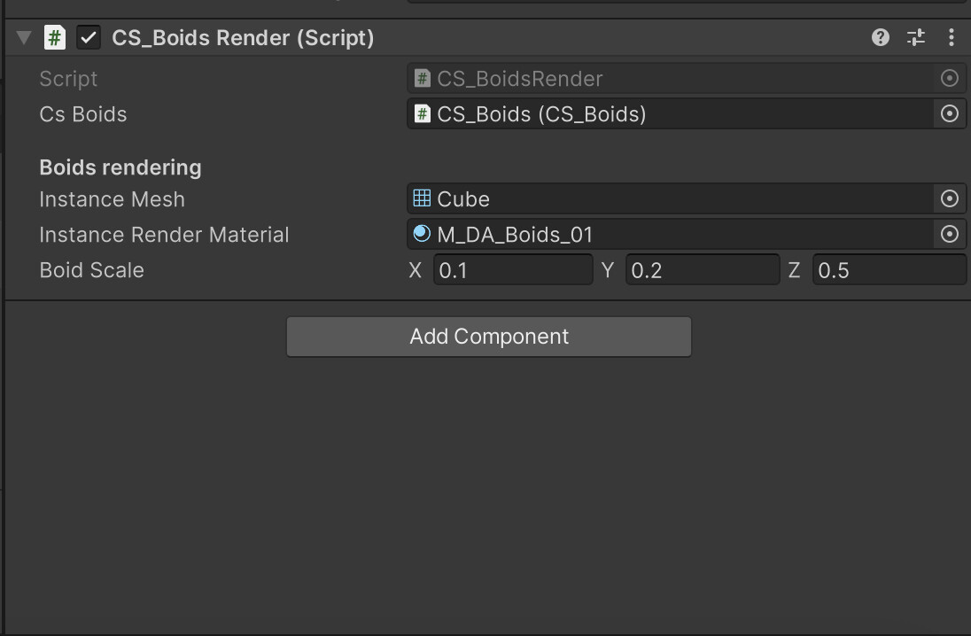
Example: GPU Instancing usage

struct Attributes
{
    float4 positionOS : POSITION;
    UNITY_VERTEX_INPUT_INSTANCE_ID
};

struct Varyings
{
    float4 positionCS : SV_POSITION;
    UNITY_VERTEX_INPUT_INSTANCE_ID // needed only if fragment needs instanced props
};

UNITY_INSTANCING_BUFFER_START(Props)
    UNITY_DEFINE_INSTANCED_PROP(float4, _Color)
UNITY_INSTANCING_BUFFER_END(Props)

Varyings vert(Attributes IN)
{
    Varyings OUT;

    UNITY_SETUP_INSTANCE_ID(IN);
    UNITY_TRANSFER_INSTANCE_ID(IN, OUT); // only needed if frag needs instanced props

    OUT.positionCS = UnityObjectToClipPos(IN.positionOS);
    return OUT;
}

half4 frag(Varyings IN) : SV_Target
{
...

    UNITY_SETUP_INSTANCE_ID(IN); // only needed if accessing instanced props here
...

half4 col_output = SAMPLE_TEXTURE2D(_BaseMap, sampler_BaseMap, IN.uv) * UNITY_ACCESS_INSTANCED_PROP(Props, _Color);
    return col_output;

...
}


Example: SRP Batcher usage

struct Attributes
{
    float3 positionOS : POSITION;
};

struct Varyings
{
    float4 positionCS : SV_POSITION;
    float4 color      : COLOR0;
};

CBUFFER_START(UnityPerMaterial)
    float4 _BaseColor;   // per-material color
    half _Amplitude;  // per-material scalar
CBUFFER_END

Varyings vert(Attributes IN)
{
    Varyings OUT;

    float3 posWS = TransformObjectToWorld(IN.positionOS);
    OUT.positionCS = TransformWorldToHClip(posWS);

    OUT.color = _BaseColor;
    return OUT;
}

half4 frag(Varyings IN) : SV_Target
{
    return IN.color * _Amplitude;
}

---

Vertex Deformation & Transforms within the Shader

Most vertex functions follow a four-step pattern: decode deform transform trim.

  • Decode any packed values (normals, masks)
  • Deform in object space. Use simple, branch-free math when possible
  • Transform once to world and clip space
  • Trim varyings to only what the fragment stage needs


Example: Vertex deformation pattern

struct Varyings 
{
    float4 positionCS : SV_POSITION;
    half2  uv         : TEXCOORD0;
    half3  normalWS   : TEXCOORD1; // only pass what you’ll actually use
};

Varyings Vert(Attributes IN)
{
    Varyings OUT;

    float3 nOS = normalize(IN.normalOS);

    // Deformation
    // Push vertices along normals, scaled by vertex color alpha
    float push   = IN.color.a * _PushAmount;
    float3 posOS = IN.positionOS + nOS * push;

    // Transforms
    float3 posWS = TransformObjectToWorld(posOS);
    OUT.positionCS = TransformWorldToHClip(posWS);
    OUT.normalWS   = TransformObjectToWorldNormal(nOS);

    // Demote (type cast)
    OUT.uv = (half2)IN.uv0;

    return OUT;
}

---

Mesh attributes used by Renderer components in Unity

Different Unity Renderer components consume different subsets of mesh data. Knowing which attributes are actually read helps you optimize layouts, strip unused channels, and decide where to store custom payloads.

Here’s a quick comparison:

---

With that, we’ll wrap up this article. I truly hope you now have a clearer picture and feel confident in effectively working with mesh data, as well as any custom data it may contain.

Thank you for your time and attention, and see you in the next one!


Support Decompiled Art on Patreon

Useful Technical Art Resources

***

...Game Art decompilation has begun...

Compute Shaders in Unity: Boids simulation on GPU, Shared Memory

Tutorial / 30 August 2023

Hi and welcome to Decompiled Art articles!

Within this article, we will explore the implementation of the Boids algorithm, harnessing the capabilities of compute shaders to simulate objects' group behaviour. This pattern, commonly observed among creatures like birds, fish and other animals, is known as flocking

Here's a brief glimpse of what you can anticipate at the conclusion of this article.


The movement of this group is both regular and intricate, possessing a captivating beauty that attracts people. In computer graphics, manually controlling the behaviour of each individual is impractical. To address this, an algorithm called Boids was developed to simulate group behaviour. This simulation algorithm comprises a few simple rules and is straightforward to implement.

However, in a basic implementation, it becomes necessary to check the positional relationships between all individuals. As the number of individuals increases, the computational load grows exponentially. Managing numerous individuals becomes exceedingly difficult when relying solely on the CPU. This is where the powerful parallel computing capabilities of GPUs come into play. Additionally, Unity's advanced rendering feature, GPU instancing, facilitates the rendering of vast quantities of diverse meshes.

Through this article, we will create a program that utilizes these Unity GPU capabilities to control and render numerous Boid objects.


It's highly recommended following along after getting yourself familiar with these chapters:

Compute Shaders in Unity: GPU Computing, First Compute Shader  

Compute Shaders in Unity: Shader Core Elements, First Compute Shader Review

Compute Shaders in Unity: Multiple Kernels, Compute Buffers, CPU - GPU data flow

Compute Shaders in Unity: Processing transforms with GPU


Boids algorithm 

A swarm simulation algorithm called Boids was developed by Craig Reynolds in 1986 as a means to simulate the collective motion and behaviour of entities in a group, inspired by the movements observed in flocks of birds. Reynolds aimed to create a simple and elegant model that could replicate the natural patterns observed in group dynamics.

The term "Boids" is a play on the words "bird-oid objects" and refers to the entities within the simulation. The algorithm's primary focus is on three key behaviours: separation, alignment, and cohesion.

  • Separation: Each Boid aims to maintain a safe distance from its neighbouring Boids, avoiding collisions and overcrowding.
  • Alignment: Boids attempt to match the average direction and speed of nearby Boids, resulting in collective alignment of movement.
  • Cohesion: Boids strive to move towards the center of mass of nearby Boids, promoting group cohesion.

Controlling these individual elements enables us to program the flock movement.


Sample implementation elements

The sample implementation will consist of these elements:

  1. CS_Boids.cs: This script oversees the execution of the compute shader (dispatching) and is accountable for simulating boids.

  2. CS_Boids.compute: A compute shader that executes calculations required for boids simulation.

  3. CS_BoidsRender.cs: This script responsible for custom approach to render each boid visual element.

  4. S_Boid.hlsl: A shader to be used for Boids rendering.


CS_Boids.cs

Let's start with adding variables and elements that will describe & control boid behaviour. 

First, we need a struct that will hold (per boid) velocity and position data

[System.Serializable]
struct BoidData
{
    public Vector3 velocity;
    public Vector3 position;
}


Next, add a property to control the total amount of boids to be rendered/simulated.

Range(128, 60000)]
[SerializeField] private int boidsCount = 5000;


Earlier, we introduced components tasked with simulating behaviors (Cohesion, Alignment, Separation, abbreviated as CAS). Now, let's incorporate these attributes:

[Header("CAS Radius")]
[SerializeField] private float cohesionRadius = 1.0f; // Radius for applying cohesion to other individuals
[SerializeField] private float alignmentRadius = 1.0f; // Radius for applying alignment to other individuals
[SerializeField] private float separationRadius = 0.5f; // Radius for applying separation to other individuals

[Header("CAS Forces")]
[SerializeField] private float cohesionWeight = 0.5f; // Cohesion force appliance weight
[SerializeField] private float alignmentWeight = 0.5f; // Alignment force appliance weight
[SerializeField] private float separationWeight = 2.0f; // Separation force appliance weight


For boids themselves, two additional properties required: Maximum Speed and Maximum Steering Force.

[Header("Boid")]
[SerializeField] private float boidMaximumSpeed = 10.0f; // Boid maximum speed
[SerializeField] private float boidMaxSteeringForce = 1.0f; // Boid maximum steering force


Simulation itself should have certain properties to be defined. These include: Simulation Center, Dimensions (X, Y, Z bounds), and Bounds Avoidance Weight.

[Header("Simulation")]
[SerializeField] private Vector3 simulationCenter = Vector3.zero; // Simulation center
[SerializeField] private Vector3 simulationDimensions = new Vector3(32.0f, 32.0f, 32.0f); // Simulation dimensions
[SerializeField] private float simulationBoundsAvoidWeight = 10.0f; // Bounding avoidance weight


To store data that should be passed between CPU <--> GPU, we need two Compute Buffers.

private ComputeBuffer _boidsSteeringForcesBuffer; // Buffer for Boids steering forces values storage
private ComputeBuffer _boidsDataBuffer; // Buffer storing basic data of Boids (velocity, position, Transform, etc.)


Furthermore, a number of private properties are necessary to retain cached data:
private uint _storedThreadGroupSize; // Thread group size received from Compute Shader
private int _dispatchedThreadGroupSize; // Thread group size calculated

private int _steeringForcesKernelId; // Kernel for processing boids steering forces calculation
private int _boidsDataKernelId; // Kernel for processing boids steering forces calculation


Now, moving on to the practical aspect. Let's begin with the initialization functions aimed at preparing data associated with buffers and Compute Shader kernels.

private void Start()
{
    InitBuffer();
    InitKernels();
}


Buffers initialization.

private void InitBuffers()
{
    _boidsDataBuffer = new ComputeBuffer(boidsCount, sizeof(float) * 6); // 6 for two Vector3
    _boidsSteeringForcesBuffer = new ComputeBuffer(boidsCount, sizeof(float) * 3); // 3 for one Vector3

    // Prepare data arrays
    Vector3[] forceArr = new Vector3[boidsCount];
    BoidData[] boidDataArr = new BoidData[boidsCount];

    for (var i = 0; i < boidsCount; i++)
    {
        forceArr[i] = Vector3.zero;
        boidDataArr[i].position = Random.insideUnitSphere * 1.0f;
        boidDataArr[i].velocity = Random.insideUnitSphere * 0.1f;
    }

    // Set data to buffers
    _boidsSteeringForcesBuffer.SetData(forceArr);
    _boidsDataBuffer.SetData(boidDataArr);
}

Kernels initialization. Here we are also making sure that correct amount of threads should be used (so no "unprocessed" elements will be rendered).

private void InitKernels()
{
    _steeringForcesKernelId = boidsComputeShader.FindKernel("SteeringForcesCS");
    _boidsDataKernelId = boidsComputeShader.FindKernel("BoidsDataCS");

    boidsComputeShader.GetKernelThreadGroupSizes(_steeringForcesKernelId, out _storedThreadGroupSize, out _, out _);
    var dispatchedThreadGroupSize = boidsCount / (int)_storedThreadGroupSize;

    if (dispatchedThreadGroupSize % _storedThreadGroupSize == 0) return;
   
    while (dispatchedThreadGroupSize % _storedThreadGroupSize != 0)
    {
        dispatchedThreadGroupSize += 1;
        if (dispatchedThreadGroupSize % _storedThreadGroupSize != 0) continue;
       
        _dispatchedThreadGroupSize = dispatchedThreadGroupSize;
       
        Debug.LogFormat("Initial threads: {0}", _storedThreadGroupSize);
        Debug.LogFormat("Threads X used: {0}", _dispatchedThreadGroupSize);
        break;
    }
}

As CS_Boids script will be referenced and used by other resources (mentioned earlier), let's add several public accessors for convenient data usage. 

public ComputeBuffer GetBoidsData()
{
    return _boidsDataBuffer;
}

public int GetBoidsCount()
{
    return boidsCount;
}

public Vector3 GetSimulationCenter()
{
    return simulationCenter;
}

public Vector3 GetSimulationDimensions()
{
    return simulationDimensions;
}

Now we need a method that will process data between CPU <--> GPU and actually execute compute shader's kernels.

private void Update()
{
    Simulation(_steeringForcesKernelId, _boidsDataKernelId);
}
private void Simulation(int steeringForcesKernelId, int boidsDataKernelId)
{
    if(boidsComputeShader == null) return;

    boidsComputeShader.SetInt("_BoidsCount", boidsCount);
   
    boidsComputeShader.SetBuffer(steeringForcesKernelId, "_BoidsDataBuffer", _boidsDataBuffer);
    boidsComputeShader.SetBuffer(steeringForcesKernelId, "_BoidsSteeringForcesBufferRw", _boidsSteeringForcesBuffer);
    boidsComputeShader.SetBuffer(boidsDataKernelId, "_BoidsSteeringForcesBuffer", _boidsSteeringForcesBuffer);
    boidsComputeShader.SetBuffer(boidsDataKernelId, "_BoidsDataBufferRw", _boidsDataBuffer);

    boidsComputeShader.SetFloat("_CohesionRadius", cohesionRadius);
    boidsComputeShader.SetFloat("_AlignmentRadius", alignmentRadius);
    boidsComputeShader.SetFloat("_SeparationRadius", separationRadius);
    boidsComputeShader.SetFloat("_BoidMaximumSpeed", boidMaximumSpeed);
    boidsComputeShader.SetFloat("_BoidMaximumSteeringForce", boidMaxSteeringForce);
    boidsComputeShader.SetFloat("_SeparationWeight", separationWeight);
    boidsComputeShader.SetFloat("_CohesionWeight", cohesionWeight);
    boidsComputeShader.SetFloat("_AlignmentWeight", alignmentWeight);
    boidsComputeShader.SetFloat("_SimulationBoundsAvoidWeight", simulationBoundsAvoidWeight);

    boidsComputeShader.SetVector("_SimulationCenter", simulationCenter);
    boidsComputeShader.SetVector("_SimulationDimensions", simulationDimensions);
   
    boidsComputeShader.SetFloat("_DeltaTime", Time.deltaTime);

    boidsComputeShader.Dispatch(steeringForcesKernelId, _dispatchedThreadGroupSize, 1, 1);
    boidsComputeShader.Dispatch(boidsDataKernelId, _dispatchedThreadGroupSize, 1, 1);
}


Remember to ensure proper cleanup of the created buffer and its associated memory when the application is not running.

private void OnDestroy()
{
    ReleaseBuffer();
}
private void ReleaseBuffer()
{
    SafeReleaseBuffer(ref _boidsDataBuffer);
    SafeReleaseBuffer(ref _boidsSteeringForcesBuffer);
}
private void SafeReleaseBuffer(ref ComputeBuffer buffer)
{
    if (buffer == null) return;
    buffer.Release();
    buffer = null;
}

Now check the inspector, it should look something like this. And now we can proceed to compute shader's code (CS_Boids.compute).


CS_Boids.compute

There are two kernels that we will use for CS_Boids compute shader. One is responsible for calculating (accumulating) steering forces, produced by Cohesion, Separation, Alignment. Second kernel is used for applying that force and update boids velocity values and positions as a result.

#pragma kernel SteeringForcesCS
#pragma kernel BoidsDataCS


Next, add the BoidData struct that will hold the information about each boid, including its velocity and position in 3D space.

struct BoidData
{
   float3 velocity;
   float3 position;
};


Next, we will need a constant, that determines the number of threads in each thread group. Utilize the HLSL #define directive to establish the thread group size, ensuring that we only need to modify this value once instead of multiple times within the shader's code.

#define THREAD_GROUP_SIZE 128


In order to process boids data, create several structured buffers

// Boids read-only structured buffer
StructuredBuffer<BoidData> _BoidsDataBuffer;

// Boids read-write structured buffer
RWStructuredBuffer<BoidData> _BoidsDataBufferRw;

// Boids steering forces buffer
StructuredBuffer<float3> _BoidsSteeringForcesBuffer;

// Read-write boids steering forces buffer
RWStructuredBuffer<float3> _BoidsSteeringForcesBufferRw;


Declare this set of parameters, that will represent boids-related data.

int _BoidsCount; // Total boids count

float _DeltaTime;      // Time elapsed since the previous frame

float _SeparationRadius; // Radius for applying separation to other individuals
float _AlignmentRadius; // Radius for applying alignment to other individuals
float _CohesionRadius;  // Radius for applying cohesion to other individuals

float _BoidMaximumSpeed;
float _BoidMaximumSteeringForce;

float _SeparationWeight;  // Separation force appliance weight
float _AlignmentWeight; // Alignment force appliance weight
float _CohesionWeight;  // Cohesion force appliance weight

float4 _SimulationCenter;
float4 _SimulationDimensions;
float _SimulationBoundsAvoidWeight;


Next, we will need two utility functions. 

Limit() function limits the magnitude of a given 3D vector to a specified maximum value. It calculates the squared length of the vector and compares it with the square of the maximum value. If the squared length is greater than the squared maximum value and is also greater than zero, it calculates the magnitude of the vector, scales it down to the specified maximum, and returns the scaled vector. Otherwise, it returns the original vector.

float3 limit(float3 vec, float max)
{
   float lengthSquared = dot(vec, vec);
   
   if (lengthSquared > max * max && lengthSquared > 0)
   {
      float length = sqrt(lengthSquared); // magnitude
      return vec.xyz * (max / length);
   }
   return vec.xyz;
}


CheckSimulationBounds() function is responsible for handling the behavior of a boid upon reaching the simulation boundaries.

float3 CheckSimulationBounds(float3 position)
{
   float3 wc = _SimulationCenter.xyz;
   float3 ws = _SimulationDimensions.xyz;

   float3 acc = float3(0, 0, 0);

   acc.x = (position.x < wc.x - ws.x * 0.5) ? 1.0 : ((position.x > wc.x + ws.x * 0.5) ? -1.0 : 0.0);
   acc.y = (position.y < wc.y - ws.y * 0.5) ? 1.0 : ((position.y > wc.y + ws.y * 0.5) ? -1.0 : 0.0);
   acc.z = (position.z < wc.z - ws.z * 0.5) ? 1.0 : ((position.z > wc.z + ws.z * 0.5) ? -1.0 : 0.0);


   return acc;
}

To proceed with compute shader code review, we need to introduce an interesting concept called Shared Memory Array.

Shared memory is a small, fast-access memory space that is shared among threads within a single thread group. It is physically located on the GPU chip and is much faster to access compared to global memory, which is off-chip. Shared memory is used to hold frequently accessed data that needs to be shared among threads within the same group. We barrely touched this concept in Compute Shaders in Unity: Shader Core Elements, First Compute Shader Review article.

Incorporate the following code, which establishes a shared memory array referred to as "boid_data." This array serves as a storage unit for boid-related information within the thread group. This utilization of shared memory is a crucial optimization strategy in GPU programming, designed to improve memory access patterns and reduce data retrieval delays.

groupshared BoidData boid_data[THREAD_GROUP_SIZE];


Back to compute shader code.

SteeringForcesCS kernel calculates the steering forces acting on each boid based on separation, alignment, and cohesion. It iterates over all boids and computes the forces acting on the current boid due to nearby boids within specified radius. The calculated forces are adjusted, normalized, and limited as required. The resulting forces are accumulated to produce the final steering force applied to the boid.

[numthreads(THREAD_GROUP_SIZE, 1, 1)]
void SteeringForcesCS (
   uint3 d_tid : SV_DispatchThreadID, // thread group unique ID
   uint  gi : SV_GroupIndex          // One-dimensional version of SV_GroupThreadID ranging from 0 to 255
)
{
   const unsigned int P_ID = d_tid.x; // Self ID
   const float3 P_position = _BoidsDataBuffer[P_ID].position; // Self position
   const float3 P_velocity = _BoidsDataBuffer[P_ID].velocity; // Self velocity

   //Resulting steering force
   float3 force = float3(0, 0, 0);

   //Position offsets influenced by cohesion, alignment, and separation
   float3 separationPositionOffset = float3(0, 0, 0);
   float3 alignmentPositionOffset = float3(0, 0, 0);
   float3 cohesionPositionOffset = float3(0, 0, 0);

   //Cumulative count of boids that need to be influenced by cohesion, alignment, and separation
   int separationBoidsCount = 0;
   int alignmentBoidsCount = 0;
   int cohesionBoidsCount = 0;

   //Accumulated steering forces
   float3 separationSteering = float3(0, 0, 0);
   float3 alignmentSteering = float3(0, 0, 0);
   float3 cohesionSteering = float3(0, 0, 0);

   // Loop unrolling
    [loop]
    for (uint n_block_id = 0; n_block_id < (uint)_BoidsCount; n_block_id += THREAD_GROUP_SIZE)
    {
        boid_data[gi] = _BoidsDataBuffer[n_block_id + gi];
        GroupMemoryBarrierWithGroupSync();


        // Conditional execution and memory coalescing
        [unroll]
        for (int N_tile_ID = 0; N_tile_ID < THREAD_GROUP_SIZE; N_tile_ID++)
        {
           const float3 N_position = boid_data[N_tile_ID].position;
           const float3 N_velocity = boid_data[N_tile_ID].velocity;


            const float3 diff = P_position - N_position; // position difference between current and other boids
            const float dist = sqrt(dot(diff, diff)); // distance difference between current and other boids


           //Separation
            if (dist > 0.0 && dist <= _SeparationRadius)
            {
                float3 repulse = normalize(P_position - N_position);
                repulse /= dist;
                separationPositionOffset += repulse;
                separationBoidsCount++;
            }


           //Alignment
            if (dist > 0.0 && dist <= _AlignmentRadius)
            {
                alignmentPositionOffset += N_velocity;
                alignmentBoidsCount++;
            }


           //Cohesion
            if (dist > 0.0 && dist <= _CohesionRadius)
            {
                cohesionPositionOffset += N_position;
                cohesionBoidsCount++;
            }
        }
       
        GroupMemoryBarrierWithGroupSync();
    }  
   
   if (separationBoidsCount > 0)
   {
      separationSteering = separationPositionOffset / (float)separationBoidsCount;     // Calculate the average
      separationSteering = normalize(separationSteering) * _BoidMaximumSpeed; // Adjust to maximum speed
      separationSteering = separationSteering - P_velocity;           // Calculate steering force
      separationSteering = limit(separationSteering, _BoidMaximumSteeringForce); // Limit the steering force
   }
   
   if (alignmentBoidsCount > 0)
   {
      alignmentSteering = alignmentPositionOffset / (float)alignmentBoidsCount;    
      alignmentSteering = normalize(alignmentSteering) * _BoidMaximumSpeed;
      alignmentSteering = alignmentSteering - P_velocity;          
      alignmentSteering = limit(alignmentSteering, _BoidMaximumSteeringForce);
   }
   
   if (cohesionBoidsCount > 0)
   {
      cohesionPositionOffset = cohesionPositionOffset / (float)cohesionBoidsCount;    
      cohesionSteering = cohesionPositionOffset - P_position;      
      cohesionSteering = normalize(cohesionSteering) * _BoidMaximumSpeed;
      cohesionSteering = cohesionSteering - P_velocity;          
      cohesionSteering = limit(cohesionSteering, _BoidMaximumSteeringForce);
   }
   
   //Pass accumulated steering forces to resulting value
   force += alignmentSteering * _AlignmentWeight;
   force += cohesionSteering * _CohesionWeight;  
   force += separationSteering * _SeparationWeight;  
   
   _BoidsSteeringForcesBufferRw[P_ID] = force;
}

In addition to the computations that result in the accumulation of steering forces, there are two additional aspects to highlight.

 Loop unrolling is an optimization technique where a loop is manually expanded or unwound into multiple iterations. This reduces the overhead of loop control and improves memory access patterns, potentially leading to better parallelism and performance. In other words, instead of having a loop that iterates through a range of values, you manually write out the loop's body multiple times. The concept of loop unrolling is implemented with [loop] and [unroll] directives.

GroupMemoryBarrierWithGroupSync() method is a synchronization mechanism used in HLSL (High-Level Shading Language) within compute shaders to ensure proper memory visibility and synchronization between threads within a thread group. 

Here's a simplified flow of how GroupMemoryBarrierWithGroupSync() works:

  1. Threads within a thread group execute code.
  2. Before a GroupMemoryBarrierWithGroupSync() is encountered, threads perform memory reads and writes.
  3. Threads reach the barrier and pause execution.
  4. The barrier ensures that all previous memory operations are completed before allowing threads to proceed.
  5. Once all threads within the thread group reach the barrier, they can continue executing code.


BoidsDataCS kernel handles the updates to boid velocity and position based on the calculated steering forces. It reads the current boid data and the associated steering force from the buffers. It also applies a repelling force if the boid is approaching the simulation boundaries. The updated velocity and position are calculated and written back to the buffer.

[numthreads(THREAD_GROUP_SIZE, 1, 1)]
void BoidsDataCS(uint3 DTid : SV_DispatchThreadID) // Thread-wide unique ID
{
   const unsigned int p_id = DTid.x;          // Self ID
                                           
   BoidData boidData = _BoidsDataBufferRw[p_id];   // Read current Boid data
   float3 force = _BoidsSteeringForcesBuffer[p_id]; // Read steering force
   
   // Apply repelling force when approaching simulation bounds
   force += CheckSimulationBounds(boidData.position) * _SimulationBoundsAvoidWeight;

   boidData.velocity += force * _DeltaTime;          // Apply steering force to velocity
   boidData.velocity = limit(boidData.velocity, _BoidMaximumSpeed); // Limit velocity
   boidData.position += boidData.velocity * _DeltaTime;     // Update position
                                           
   _BoidsDataBufferRw[p_id] = boidData;            // Write calculation result
}


CS_BoidsRender.cs

This script is responsible for rendering boid entities using GPU instancing. It works in conjunction with the CS_Boids script, which manages the boid simulation.

First, let's add several properties:

  • csBoids (SerializeField): A reference to the CS_Boids script component responsible for managing boid simulation data.
[SerializeField] private CS_Boids csBoids;


  • boidScale (SerializeField): A vector representing the scale of the rendered boid objects.
  • instanceMesh (SerializeField): A reference to the mesh that will be instanced for rendering.
  • instanceRenderMaterial (SerializeField): A reference to the material used for rendering the instanced boid objects.
[SerializeField] private Mesh instanceMesh;
[SerializeField] private Material instanceRenderMaterial;
[SerializeField] public Vector3 boidScale = new Vector3(0.2f, 0.3f, 0.6f);


  • _supportsInstancing: A boolean indicating whether the hardware supports GPU instancing.
  • _instanceMeshIndexCount: The number of indices in the mesh being instanced.
  • _boidsCount: The total number of boids in the simulation.
private bool _supportsInstancing;
private uint _instanceMeshIndexCount;
private uint _boidsCount;


  • _simulationBounds: A bounding area defining the spatial extent of the simulation.
private Bounds _simulationBounds;


  • _args: An array of arguments used for GPU instancing. These include indices per instance, instance count, start index location, base vertex location, and start instance location.
private readonly uint[] _args = new uint[5] { 0, 0, 0, 0, 0 };

  • _argsBuffer: A ComputeBuffer used for transferring the _args data to the GPU.
private ComputeBuffer _argsBuffer;


  • BoidDataBuffer (static readonly): The shader property ID for the boid data buffer.
  • Scale (static readonly): The shader property ID for the object scale.
private static readonly int BoidDataBuffer = Shader.PropertyToID("_BoidDataBuffer");
private static readonly int Scale = Shader.PropertyToID("_BoidScale");


Save the C# script and check the inspector. Picture should be similar to this one. 


Awake() method retrieves the CS_Boids script component when the script is initialized.

private void Awake()
{
    csBoids = GetComponent<CS_Boids>();
}


In Start() we initialize various values, such as checking for GPU instancing support, obtaining the mesh's index count, and getting the total boids count from the CS_Boids script.


private void Start()
{
    InitValues();
    GetSimulationBounds();
}


InitValues() method initializes values required for rendering, including GPU instancing support, mesh index count, and boids count. It also creates the _argsBuffer for GPU instancing arguments.


private void InitValues()
{
    _supportsInstancing = SystemInfo.supportsInstancing;
    _instanceMeshIndexCount = (instanceMesh != null ? instanceMesh.GetIndexCount(0) : 0);
    _boidsCount = (uint)csBoids.GetBoidsCount();

    _argsBuffer = new ComputeBuffer(1, _args.Length * sizeof(uint),
        ComputeBufferType.IndirectArguments);
}


In Update() method we need to check whether conditions are met for rendering, and if so, calls the RenderInstancedMesh() method.


private void Update()
{
    if (instanceRenderMaterial == null || csBoids == null || !_supportsInstancing)
        return;
   
   RenderInstancedMesh();
}


Keep in mind to release the _argsBuffer when the script is disabled or destroyed.


private void OnDisable()
{
    _argsBuffer?.Release();
}


RenderInstancedMesh() method is used to render the instanced mesh using GPU instancing. It updates the _args buffer, creates a MaterialPropertyBlock for shader properties, and draws the instanced mesh using GPU instancing and the provided material.


private void RenderInstancedMesh()
{
    // Update the arguments buffer
    _args[0] = _instanceMeshIndexCount;
    _args[1] = _boidsCount;
    _argsBuffer.SetData(_args);

    // Create a MaterialPropertyBlock
    var propertyBlock = new MaterialPropertyBlock();

    // Set the boid data buffer and scale property in the property block
    propertyBlock.SetBuffer(BoidDataBuffer, csBoids.GetBoidsData());
    propertyBlock.SetVector(Scale, boidScale);

    // Draw the mesh using GPU instancing with the property block
    Graphics.DrawMeshInstancedIndirect(instanceMesh, 0, instanceRenderMaterial, _simulationBounds, _argsBuffer, 0, propertyBlock);
}


With GetSimulationBounds() we can get simualtion bounds data.


private void GetSimulationBounds()
{
    // Define the bounding area
    _simulationBounds = new Bounds
    (
        csBoids.GetSimulationCenter(),
        csBoids.GetSimulationDimensions()
    );
}

S_Boid.hlsl

S_Boid shader is used for rendering dynamic boids instances using GPU instancing. The particular shader is designed to render the boids based on their positions, velocities, and other properties stored in a structured buffer.

Before adiving into code, we have to familiarize ourselves with concept of angles naming, used in this shader (Pitch, Roll, Yaw).

"Pitch," "Roll," and "Yaw" are terms used to describe the rotational movements of an object in three-dimensional space. These terms are commonly used in aviation, aerospace, robotics, and computer graphics to define the orientation of an object or vehicle. In relation to XYZ coordinates:

  • Pitch - X coordinate
  • Roll - Y coordinate
  • Yaw - Z coordinate


Shifting our focus to the coding aspect...

Create a new Unlit shader as it already includes all fundamental shader code. Now, let's modifiy it.

Add instancing_options #pragma. It indicates that GPU instancing will be used with procedural setup.

#pragma instancing_options procedural: setup


We also need a special struct named BoidData. It contains the per-instance data for each "Boid," including velocity and position. Define it after standard appdata and v2f structs.

struct BoidData
{
    half3 velocity;
    half3 position;
};


Next, define a structured buffer that holds the Boid data (velocity and position) for each instance.

StructuredBuffer<BoidData> _BoidDataBuffer;


A uniform variable that holds the scale of each Boid instance.

half3 _BoidScale;


You've noticed that there's a new precision is used (half). Its commonly used in situations where memory consumption and performance are important factors, such as mobile devices or (in our case) massive objects simulations.

When choosing between half and float in HLSL shaders, you need to consider the trade-off between precision and performance. If your shader requires high precision and you're not constrained by memory or processing power, you might opt for float. On the other hand, if memory efficiency and performance are critical, half could be a better choice. It's important to note that not all GPUs support half natively, so the level of hardware support can also influence your decision.

In order to get a 4x4 rotation matrix, let's create a utility function named eulerToMatrix(float3 inputAngles). It would be a function that calculates a rotation matrix from Euler angles (yaw, pitch, roll) and returns it.

half4x4 eulerToMatrix(float3 inputAngles)
{
       // Calculate sine and cosine values for each angle
 half cosYaw = cos(inputAngles.y);
 half sinYaw = sin(inputAngles.y);
 half cosPitch = cos(inputAngles.x);
 half sinPitch = sin(inputAngles.x);
 half cosRoll = cos(inputAngles.z);
 half sinRoll = sin(inputAngles.z);

 // Create a 4x4 rotation matrix to hold the result
 // Fill in the rotation matrix elements using the calculated values
 // Yaw-Pitch-Roll (Ry-Rx-Rz)
 return half4x4(
     cosYaw * cosRoll + sinYaw * sinPitch * sinRoll, -cosYaw * sinRoll + sinYaw * sinPitch * cosRoll, sinYaw * cosPitch, 0,
     cosPitch * sinRoll, cosPitch * cosRoll, -sinPitch, 0,
     -sinYaw * cosRoll + cosYaw * sinPitch * sinRoll, sinYaw * sinRoll + cosYaw * sinPitch * cosRoll, cosYaw * cosPitch, 0,
     0, 0, 0, 1
 );  // float4(0, 0, 0, 1) for homogeneous coordinates in the last row
}


The vertex shader processes each instance's vertex data and transforms it.

  1. It retrieves Boid data (position, velocity) using the instance ID.
  2. Extracts the position and scale values of the current instance.
  3. Calculates rotation angles based on the velocity components (yaw and pitch).
  4. Computes a rotation matrix using the calculated angles.
  5. Combines the rotation and scale in a single matrix and applies translation.
  6. Transforms the vertex position using the combined matrix.
  7. Passes the transformed vertex position and UV coordinates to the fragment shader.

Code follows:

v2f vert (appdata v)
        {
            v2f o;                

            BoidData boidData = _BoidDataBuffer[v.unity_InstanceID];

            float3 pos = boidData.position.xyz;
   half3 boidScale = _BoidScale;
           
float4x4 object2world = 0;
           
// Assign the scale value
object2world._11_22_33_44 = float4(boidScale.xyz, 1.0);
           
// Calculate the rotation around the Y-axis from the velocity
half rotY =
   atan2(boidData.velocity.x, boidData.velocity.z);
           
// Calculate the rotation around the X-axis from the velocity
half rotX =
   -asin(boidData.velocity.y / (length(boidData.velocity.xyz) + 1e-8));
           
// Calculate the rotation matrix from Euler angles (in radians)
half4x4 rotMatrix = eulerToMatrix(half3(rotX, rotY, 0));


           // Apply rotation to the matrix
object2world = mul(rotMatrix, object2world);
           
// Apply translation to the matrix
object2world._14_24_34 += pos.xyz;
           
v.vertex = mul(object2world, v.vertex);    
           o.vertex = UnityObjectToClipPos(v.vertex);
            o.uv = TRANSFORM_TEX(v.uv, _MainTex);
           
            return o;
        }


The fragment shader simply samples the main texture using UV coordinates and returns the resulting color.

half4 frag (v2f i) : SV_Target
{
    half4 col = tex2D(_MainTex, i.uv);
    return col;
}

There might be a specific confusion surrounding values like object2world._14_24_34. Let's comprehensively break it down now.

In our scenario, we're assigning values to matrices for transformation, rotation, and scaling.

  • Translation matrix is used to move or position objects in three-dimensional space. A translation matrix is usually represented as a 4x4 matrix, known as a homogeneous transformation matrix. This matrix includes elements that correspond to the X, Y, and Z translations, as well as a fourth row used for perspective transformations.
  • Rotation matrix is a 3x3 or 4x4 matrix that is used to represent the orientation of an object in three-dimensional space. Its designed to perform rotations around one or more coordinate axes, such as the X, Y, and Z axes. It is constructed based on trigonometric functions like sine and cosine to encode the rotation angles. A 3x3 rotation matrix is generally used for rotations in three-dimensional space, while a 4x4 matrix can also include translation and scaling transformations in addition to rotation.
  • Scale matrix is a diagonal matrix used to uniformly scale objects in three-dimensional space. Scale matrices are often represented as 3x3 or 4x4 matrices and defined by the scaling factors applied along the X, Y, and Z axes. When a vector is multiplied by a scale matrix, its individual components are multiplied by the corresponding scaling factors. This results in uniformly changing the size of an object while maintaining its proportions.


Concerning these seemingly unusual numbers like _14_24_34, they correspond to specific components within the matrix. 14, 24, 34 stands for particular component address. 

Please review this picture to visually understand the labeling/addressing/positioning of each element within the matrix (General matrix components arrangement).

The elements tX, tY, and tZ correspond to the X, Y, and Z coordinates, respectively (Translation matrix).

Similarly, the components sX, sY, and sZ correspond to the X, Y, and Z coordinates (Scaling matrix).

A rotation matrix is designed to perform rotations around one or more coordinate axes, such as the X, Y, and Z axes. Speaking of setting components' values:

Once the rotation matrix is established, you can apply it to vertices or vectors to achieve the desired rotation effect. 

Whew, now we're all set to bring everything together and check out the resulting outcome (and of course, play around with values and visuals).


Congratulations! You've done it! Boids movement powered by GPU capabilities.

Thanks a lot for attention, and until the next time!


Support Decompiled Art on Patreon 

(and get source files for this article)


***

FOLLOW AND CHECK FOR UPDATES:

Decompiled Art YouTube

Decompiled Art Instagram

Decompiled Art Twitter

Decompiled Art Facebook

***

...Game Art decompilation has begun...

Compute Shaders in Unity: Processing transforms with GPU

Tutorial / 04 July 2023

Hi and welcome to Decompiled Art articles!

As we progress, we're entering a more practical phase. It may have taken some time, but I believe you can agree that understanding the fundamentals of GPU Computing and its implementation within Unity is crucial. Without this foundation, we would be lacking the necessary groundwork. So, let's now delve into the exciting topic of how the GPU can assist us in processing transforms!


To follow along, please make sure to check these chapters:

Compute Shaders in Unity: GPU Computing, First Compute Shader  

Compute Shaders in Unity: Shader Core Elements, First Compute Shader Review

Compute Shaders in Unity: Multiple Kernels, Compute Buffers, CPU - GPU data flow


When it comes to processing transforms (and other quantity-dependent operations) in Unity, there are key differences between using the CPU and the GPU, particularly with compute shaders. 

The CPU is slower in transform processing compared to the GPU for a few reasons:

  • Parallelism: GPUs have thousands of cores designed for parallel processing, allowing them to handle multiple transform operations simultaneously. CPUs, with fewer cores optimized for sequential execution, cannot match the parallel computing power of GPUs.
  • Hardware Acceleration: GPUs are specialized hardware with dedicated resources for parallel computing. They are optimized for handling large amounts of data efficiently, unlike CPUs, which have a more balanced design for general-purpose computing.
  • Memory Bandwidth: GPUs typically have faster memory access and higher memory bandwidth, enabling them to handle the data-intensive nature of transform processing more efficiently than CPUs.

To sum up, GPU's parallel architecture, hardware acceleration and efficient memory access make it faster for large amount of transforms processing compared to the CPU.

In this article, we will examine three examples of how to leverage GPUs for transform manipulations, specifically focusing on tweaking position values.

Here, you can get a sneak peek of the results from all three samples in a fast-forward preview:

In each sample, we will process a specified number of spawned objects (such as basic spheres) and apply specific positioning behaviors to them.


Basic sample

Let's begin with the simplest example, where our goal can be divided into two parts:

  1. Setting the initial position for each spawned object.
  2. Adding controls to give each object its own offsets and exposing controls to UI interactive elements.


GPU processing transforms, Basic sample: Compute shader

#pragma kernel TransformsBasic
struct SpawnedObjectData
{
    float3 position;
};


RWStructuredBuffer<SpawnedObjectData> spawnedObjectsData;
RWStructuredBuffer<SpawnedObjectData> spawnedObjectsDataInit;


float resolution;
float offsetMultiplier;


float generateRandom (float input, float seed = 0.538)
{
    float randomOutput = frac(sin(input + seed) * 142631.6548);
    return randomOutput;
}


[numthreads(64,1,1)]
void TransformsBasic (uint3 id : SV_DispatchThreadID)
{    
    SpawnedObjectData spawnedObjectData;    

    //RESET X-POSITION
    spawnedObjectData.position = spawnedObjectsDataInit[id.x].position;
        
    const float randomOffset = generateRandom(id.x) * offsetMultiplier;
    spawnedObjectData.position.x += randomOffset;
    spawnedObjectData.position.y += randomOffset;
 
    spawnedObjectsData[id.x] = spawnedObjectData;
}


SpawnedObjectData struct

struct SpawnedObjectData
{
    float3 position;
};

The purpose of this struct is to store, modify, and set position values for an individual spawned object. It consists of a single member, position, which is of type float3 (Vector3 analogue).


Read-write structured buffers

RWStructuredBuffer<SpawnedObjectData> spawnedObjectsData;
RWStructuredBuffer<SpawnedObjectData> spawnedObjectsDataInit;

spawnedObjectsData - read-write structured buffer that holds the data of the spawned objects. It allows the shader to read and modify the position of each object.

spawnedObjectsDataInit - read-write structured buffer used as an initial copy of the spawned objects' data. It is utilized to revert XY-positions of each object to initial values.


generateRandom() utility function

float generateRandom (float input, float seed = 0.538)
{
    float randomOutput = frac(sin(input + seed) * 142631.6548);
    return randomOutput;
}

A function that generates a random value based on an input value and an optional seed. The implementation utilizes a sine function and fractional part to produce pseudo-random numbers.


Kernel 

[numthreads(64,1,1)]
void TransformsBasic (uint3 id : SV_DispatchThreadID)
{    
    SpawnedObjectData spawnedObjectData;    

    //RESET X-POSITION
    spawnedObjectData.position = spawnedObjectsDataInit[id.x].position;
        
    const float randomOffset = generateRandom(id.x) * offsetMultiplier;
    spawnedObjectData.position.x += randomOffset;
    spawnedObjectData.position.y += randomOffset;
    
    spawnedObjectsData[id.x] = spawnedObjectData;
}

Inside the kernel, we store the position data (Vector3) of the spawned object in the position variable of a float3 struct. Using the offsetMultiplier and the output of the generateRandom() function, we apply the resulting offsets to X and Y coordinates. Finally, we set the modified result back to the spawnedObjectsData array at index id.x, where id.x corresponds to each processed spawned object.


GPU processing transforms basic sample: C# script

using System.Collections.Generic;
using UnityEngine;


namespace CS_Transforms
{
    public class CS_TransformsBasic : MonoBehaviour
    {
        [SerializeField] private ComputeShader computeShader;
        [SerializeField] private string kernelName = "CSMain";
        [SerializeField] private GameObject objectToSpawn;
        [SerializeField] private int spawnGridResolution = 1;
        public float offsetMultiplier = 0.0f;

        private uint _threadsGroupSizeX;

        private List<GameObject> _spawnedObjects;

        private bool _initDataSet;
        
        private int _kernelHandle;
        private ComputeBuffer _computeBuffer;
        private ComputeBuffer _computeBufferInit;
        
        private SpawnedObjectData[] _spawnedObjectsData;
        private SpawnedObjectData[] _spawnedObjectsDataInit;

        private void Awake()
        {
            SetupSpawnedObjects();
            SetupComputeShader();
        }

        private void OnDestroy()
        {
            _computeBuffer.Dispose();
            _computeBufferInit.Dispose();
        }

        private void SetupSpawnedObjects()
        {
            _spawnedObjects = new List<GameObject>();

            _spawnedObjectsData = new SpawnedObjectData[spawnGridResolution * spawnGridResolution];
            _spawnedObjectsDataInit = new SpawnedObjectData[spawnGridResolution * spawnGridResolution];

            for (var i = 0; i < spawnGridResolution; i++)
            {
                for (var j = 0; j < spawnGridResolution; j++)
                {
                    SpawnObject(i,j);
                }
            }
        }
        private void SpawnObject(int x, int y)
        {
            var spawnPos = new Vector3(x, y, 0f);
            GameObject spawnGo = Instantiate(objectToSpawn, spawnPos, Quaternion.identity);
            
            _spawnedObjects.Add(spawnGo);

            var spawnObjectData = new SpawnedObjectData();
            spawnObjectData.Position = spawnGo.transform.position;

            _spawnedObjectsData[x * spawnGridResolution + y] = spawnObjectData;
            _spawnedObjectsDataInit[x * spawnGridResolution + y] = spawnObjectData;
        }

        public void SetupComputeShader()
        {
            _kernelHandle = computeShader.FindKernel(kernelName);
            computeShader.GetKernelThreadGroupSizes(_kernelHandle, out _threadsGroupSizeX, out _, out _);

            _computeBuffer = new ComputeBuffer(_spawnedObjectsData.Length, sizeof(float) * 3);
            _computeBuffer.SetData(_spawnedObjectsData);

            if (!_initDataSet)
            {
                _computeBufferInit = new ComputeBuffer(_spawnedObjectsData.Length, sizeof(float) * 3);
                _computeBufferInit.SetData(_spawnedObjectsData);
                
                computeShader.SetBuffer(_kernelHandle, "spawnedObjectsDataInit", _computeBuffer);
                
                _initDataSet = true;
            }

            //SET COMPUTE SHADER DATA
            computeShader.SetBuffer(_kernelHandle, "spawnedObjectsData", _computeBuffer);
            computeShader.SetFloat("resolution", _spawnedObjectsData.Length);
            computeShader.SetFloat("offsetMultiplier", offsetMultiplier);
        
            ShaderDispatch();
        
            //GET DATA FROM COMPUTE SHADER
            _computeBuffer.GetData(_spawnedObjectsData);
        
            for (var i = 0; i < _spawnedObjects.Count; i++)
            {
                var obj = _spawnedObjects[i];
                var spawnedObjectData = _spawnedObjectsData[i];
                obj.transform.position = spawnedObjectData.Position;
            }
        }

        private void ShaderDispatch()
        {
            computeShader.Dispatch(_kernelHandle, (int)(_spawnedObjectsData.Length /_threadsGroupSizeX),1,1);
        }

        private struct SpawnedObjectData
        {
            public Vector3 Position;
        }
    }
}

First, we define some serialized fields that can be accessed and modified in the Unity Editor. These fields include the compute shader itself (computeShader), the name of the kernel to be executed (kernelName), the prefab for the object to be spawned (objectToSpawn), and the resolution of the spawn grid (spawnGridResolution). Additionally, we have a public float variable (offsetMultiplier) that controls the offset applied to the objects' positions.

Also, script includes a nested SpawnedObjectData struct, which holds the position data for each spawned object.

private struct SpawnedObjectData
{
    public Vector3 Position;
}

_spawnedObjectsData and _spawnedObjectsDataInit are used to store current and initial spawned objects data respectfully. 

During the Awake() method, the script initializes the spawned objects and sets up the compute shader. 

The SetupSpawnedObjects() method iterates over the spawn grid resolution to spawn objects and assigns their initial positions.

The SetupComputeShader() method sets up the compute shader by finding the kernel handle, retrieving the thread group size, creating and populating compute buffers with the object data, and setting the necessary shader data. 

The ShaderDispatch() method dispatches the compute shader for execution.

After the compute shader has executed, the script retrieves the updated object data from the compute buffer. It then iterates over the spawned objects, updating their positions based on the computed results.

For this sample and its visual representation, I have created a basic UI structure that includes controls for setting updated values and manually dispatching a compute shader.

C# script used by this controls is pretty straightforward and looks like this:

public class UiTransformsBasicSetOffsetMultiplier : MonoBehaviour
{
    [SerializeField] private Slider offsetMultiplierValue;
    [SerializeField] private CS_TransformsBasic csTransformsBasic;

    private void Awake()
    {
        if(csTransformsBasic)
            csTransformsBasic.offsetMultiplier = offsetMultiplierValue.value;
    }

    public void SetOffsetMultiplier()
    {
        csTransformsBasic.offsetMultiplier = offsetMultiplierValue.value;
        csTransformsBasic.SetupComputeShader();
    }
}

With all the setup in place (as discussed in one of the previous articles), try adjusting the value of the OffsetMultiplier property and observe the final result.

Sine Movement sample

The next two samples will concentrate on dynamic adjustments of object positions during "runtime". Specifically, this one will demonstrate changing the position of each object using the Sine wave function.

GPU processing transforms, Sine wave sample: Compute shader

#pragma kernel TransformsSineMovement

struct SpawnedObjectData
{
    float3 position;
};

float time;
float amplitude;
float frequency;
float speed;

float resolution;

RWStructuredBuffer<SpawnedObjectData> spawnedObjectsData;

[numthreads(64,1,1)]
void TransformsSineMovement (uint3 id : SV_DispatchThreadID)
{    
    SpawnedObjectData spawnedObjectData = spawnedObjectsData[id.x];

    //POSITION CHANGES PROCESSING
    spawnedObjectData.position.y += sin(-(id.x/resolution) * frequency + time * speed) * amplitude;
    
    spawnedObjectsData[id.x] = spawnedObjectData;
}

In this compute shader, additional variables have been introduced to control the movement behavior of the objects. These variables, namely amplitude, frequency, speed, and time, are used as arguments for the Sine function. 

  • amplitude - determines the maximum displacement from the initial position.
  • frequency - controls the rate of oscillation. 
  • speed - determines how quickly the objects move. 

time variable allows for passing the results of the compute shader during runtime, enabling dynamic adjustments to the object positions.

Kernel

[numthreads(64,1,1)]
void TransformsSineMovement (uint3 id : SV_DispatchThreadID)
{    
    SpawnedObjectData spawnedObjectData = spawnedObjectsData[id.x];

    //POSITION CHANGES PROCESSING
    spawnedObjectData.position.y += sin(-(id.x/resolution) * frequency + time * speed) * amplitude;
    
    spawnedObjectsData[id.x] = spawnedObjectData;
}

Within the kernel, the position (Y coordinate in particular) of the object is updated based on the Sine wave formula. 

Finally, the modified position is written back to the spawnedObjectsData buffer.


GPU processing transforms, Sine wave sample: C# script

public class CS_TransformsSineMovement : MonoBehaviour
{
    [SerializeField] private ComputeShader computeShader;
    [SerializeField] private string kernelName = "CSMain";
    [SerializeField, Range(1, 10)] private int frameSkipping = 1;
    [SerializeField] private GameObject objectToSpawn;
    [SerializeField] private int spawnGridResolution = 1;
    [SerializeField] private float amplitude, frequency, speed;
    
    private uint _threadsGroupSizeX;

    private List<GameObject> _spawnedObjects;

    private int _kernelHandle;
    private ComputeBuffer _computeBuffer;
    private SpawnObjectData[] _spawnedObjectsData;

    private void Awake()
    {
        SetupSpawnedObjects();
        SetupComputeShader();
    }

    private void Update()
    {
        if(Time.frameCount % frameSkipping != 0) return;
        
        computeShader.SetFloat("time", Time.time);
        computeShader.SetFloat("amplitude", amplitude);
        computeShader.SetFloat("frequency", frequency);
        computeShader.SetFloat("speed", speed);
        
        ShaderDispatch();
        
        //GET DATA FROM COMPUTE SHADER
        _computeBuffer.GetData(_spawnedObjectsData);

        for (var i = 0; i < _spawnedObjects.Count; i++)
        {
            var obj = _spawnedObjects[i];
            var spawnedObjectData = _spawnedObjectsData[i];
            obj.transform.position = spawnedObjectData.Position;
        }
    }

    private void OnDestroy()
    {
        _computeBuffer.Dispose();
    }

    private void SetupSpawnedObjects()
    {
        _spawnedObjects = new List<GameObject>();
        _spawnedObjectsData = new SpawnObjectData[spawnGridResolution * spawnGridResolution];

        for (var i = 0; i < spawnGridResolution; i++)
        {
            for (var j = 0; j < spawnGridResolution; j++)
            {
                SpawnObject(i,j);
            }
        }
    }
    
    private void SpawnObject(int x, int y)
    {
        var spawnPos = new Vector3(x, y, 0f);
        var spawnGo = Instantiate(objectToSpawn, spawnPos, Quaternion.identity);

        _spawnedObjects.Add(spawnGo);

        var spawnObjectData = new SpawnObjectData();
        spawnObjectData.Position = spawnGo.transform.position;
        
        _spawnedObjectsData[x * spawnGridResolution + y] = spawnObjectData;
    }

    private void SetupComputeShader()
    {
        _kernelHandle = computeShader.FindKernel(kernelName);
        computeShader.GetKernelThreadGroupSizes(_kernelHandle, out _threadsGroupSizeX, out _, out _);
        
        _computeBuffer = new ComputeBuffer(_spawnedObjectsData.Length, sizeof(float) * 3);

        _computeBuffer.SetData(_spawnedObjectsData);
        
        //SET COMPUTE SHADER DATA
        computeShader.SetBuffer(_kernelHandle, "spawnedObjectsData", _computeBuffer);
        computeShader.SetFloat("resolution", _spawnedObjectsData.Length);

        ShaderDispatch();

        //GET DATA FROM COMPUTE SHADER
        _computeBuffer.GetData(_spawnedObjectsData);
        
        for (var i = 0; i < _spawnedObjects.Count; i++)
        {
            var spawnedObject = _spawnedObjects[i];
            var spawnedObjectData = _spawnedObjectsData[i];
            spawnedObject.transform.position = spawnedObjectData.Position;
        }
    }

    private void ShaderDispatch()
    {
        computeShader.Dispatch(_kernelHandle, (int)(_spawnedObjectsData.Length + _threadsGroupSizeX),1,1);
    }

    private struct SpawnObjectData
    {
        public Vector3 Position;
    }
}

This script bears some resemblance to the previous one. However, the main difference lies in the usage of the Update() method to pass variable values and retrieve the modified object positions from the compute shader.

private void Update()
{
        if(Time.frameCount % frameSkipping != 0) return;
        
        computeShader.SetFloat("time", Time.time);
        computeShader.SetFloat("amplitude", amplitude);
        computeShader.SetFloat("frequency", frequency);
        computeShader.SetFloat("speed", speed);
        
        ShaderDispatch();
        
        //GET DATA FROM COMPUTE SHADER
        _computeBuffer.GetData(_spawnedObjectsData);

        for (var i = 0; i < _spawnedObjects.Count; i++)
        {
            var obj = _spawnedObjects[i];
            var spawnedObjectData = _spawnedObjectsData[i];
            obj.transform.position = spawnedObjectData.Position;
        }
}

It is important to note a helpful optimization that grants you control over the frequency at which you obtain results from the compute shader. By setting the value of the frameSkipping variable, you can specify the desired frequency, indicating a specific number of frames to be skipped when you wish to receive computational outputs.

if(Time.frameCount % frameSkipping != 0) return;

Now, let's examine the final result for this sample.


Semi-Randomized movement sample

As we reach the last sample, we bring together all the concepts we have covered thus far regarding transform processing. The outcome of this sample will be a partially random arrangement of spawned object positions, influenced by the noise property value.

GPU processing transforms, Random movement sample: Compute shader

#pragma kernel TransformsRandomMovement

struct SpawnedObjectData
{
    float3 position;
};

float time;
float noiseScale;

RWStructuredBuffer<SpawnedObjectData> spawnedObjectsData;

float random(float value, float seed)
{
    float res = frac(sin(value + seed) * 143758.5453);
    return res;
}

float3 random3(float value, float seed)
{
    return float3(random(value, seed + 0.9812),
                  random(value, seed + 0.1536),
                  random(value, seed + 0.7241));
}

[numthreads(64,1,1)]
void TransformsRandomMovement (uint3 id : SV_DispatchThreadID)
{
    float seed = id.x;
    float3 randomVec1 = random3(id.x, seed) - 0.5;
    float3 randomVec2 = random3(id.x, seed + 7.1393) - 0.5;
    float3 sinDir = normalize(randomVec1);
    float3 vec = normalize(randomVec2);
    float3 cosDir = normalize(cross(sinDir, vec));

    float scaledTime = time * 0.5 + random(id.x, seed) * 712.131234;

    // Add noise to the position calculation
    float3 noise = random3(id.x, seed + 15.8257) * noiseScale;
    float3 pos = sinDir * sin(scaledTime) + cosDir * cos(scaledTime) + noise;

    spawnedObjectsData[id.x].position = pos * 2;     
}


Helper Functions

float random(float value, float seed)
{
    float res = frac(sin(value + seed) * 143758.5453);
    return res;
}

float3 random3(float value, float seed)
{
    return float3(random(value, seed + 0.9812),
                  random(value, seed + 0.1536),
                  random(value, seed + 0.7241));
}

random() function takes a value and a seed as inputs and returns a random value between 0 and 1 using a pseudo-random number generator. 

random3() function generates a random float3 vector by calling the random() function multiple times with different seed values.


Kernel

[numthreads(64,1,1)]
void TransformsRandomMovement (uint3 id : SV_DispatchThreadID)
{
    float seed = id.x;
    float3 randomVec01 = random3(id.x, seed) - 0.5;
    float3 randomVec02 = random3(id.x, seed + 7.1393) - 0.5;
    float3 sinDir = normalize(randomVec01);
    float3 vec = normalize(randomVec02);
    float3 cosDir = normalize(cross(sinDir, vec));

    float scaledTime = time * 0.5 + random(id.x, seed) * 712.131234;

    // Add noise to the position calculation
    float3 noise = random3(id.x, seed + 15.8257) * noiseScale;
    float3 pos = sinDir * sin(scaledTime) + cosDir * cos(scaledTime) + noise;

    spawnedObjectsData[id.x].position = pos * 2;     
}

Within the kernel, two random vectors, randomVec01 and randomVec02, are generated using the random3 function and normalized. These vectors are used to define a sine direction sinDir and a cross direction cosDir.

The variable scaledTime is calculated by multiplying the time by 0.5 and adding a random value using the random() function.

Noise is added to the position calculation by generating a random float3 vector, noise, using the random3() function and scaling it by the noise scale value.

The final position, pos, is determined by combining the sinDir and cosDir directions with the noise vector.

The modified position is then stored in the position member of the SpawnedObjectData for the corresponding object in the spawnedObjectsData buffer.


GPU processing transforms, Random movement sample: C# script

using System.Collections.Generic;
using UnityEngine;

namespace CS_Transforms
{
    public class CS_TransformsRandomMovement : MonoBehaviour
    {
        [SerializeField] private ComputeShader computeShader;
        [SerializeField] private string kernelName = "CSMain";
        [SerializeField, Range(1, 10)] private int frameSkipping = 1;
        [SerializeField] private GameObject objectToSpawn;
        [SerializeField] private int objectsSpawnCount = 1;
        [SerializeField] private float noiseScale = 0.1f;

        private uint _threadsGroupSizeX;

        private List<GameObject> _spawnedObjects;

        private int _kernelHandle;
        private ComputeBuffer _computeBuffer;
        private SpawnObjectData[] _spawnedObjectsData;

        private void Awake()
        {
            SetupSpawnedObjects();
            SetupComputeShader();
        }

        private void Update()
        {
            if(Time.frameCount % frameSkipping != 0) return;
            
            computeShader.SetFloat("time", Time.time);
            computeShader.SetFloat("noiseScale", noiseScale);
        
            ShaderDispatch();
            
            //GET DATA FROM COMPUTE SHADER
            _computeBuffer.GetData(_spawnedObjectsData);
        
            for (var i = 0; i < _spawnedObjects.Count; i++)
            {
                _spawnedObjects[i].transform.position = _spawnedObjectsData[i].Position;
            }
        }

        private void OnDestroy()
        {
            _computeBuffer.Dispose();
        }

        private void SetupSpawnedObjects()
        {
            _spawnedObjects = new List<GameObject>();

            for (var i = 0; i < objectsSpawnCount; i++)
            {
                SpawnObject();
            }
            _spawnedObjectsData = new SpawnObjectData[_spawnedObjects.Count];
        }
        private void SpawnObject()
        {
            var spawnGo = Instantiate(objectToSpawn, Vector3.zero, Quaternion.identity);
            _spawnedObjects.Add(spawnGo);
        }

        private void SetupComputeShader()
        {
            _kernelHandle = computeShader.FindKernel(kernelName);
            computeShader.GetKernelThreadGroupSizes(_kernelHandle, out _threadsGroupSizeX, out _, out _);
            
            _computeBuffer = new ComputeBuffer(_spawnedObjectsData.Length, sizeof(float) * 3);

            //SET COMPUTE SHADER DATA
            computeShader.SetBuffer(_kernelHandle, "spawnedObjectsData", _computeBuffer);

            ShaderDispatch();
        }

        private void ShaderDispatch()
        {
            computeShader.Dispatch(_kernelHandle, (int)(_threadsGroupSizeX),1,1);
        }

        private struct SpawnObjectData
        {
            public Vector3 Position;
        }
    }
}

Provided script behaves the same way as previous one, but passing to the compute shader the noiseScale value by calling:

computeShader.SetFloat("noiseScale", noiseScale);

Let's examine the final result for this sample.


As we conclude this article, my sincere wish is that it has laid a solid groundwork for your comprehension of harnessing the power of GPU to process transformations.

Thanks a lot for attention, and until the next time!


Support Decompiled Art on Patreon

(and get source files for this article)


Support Decompiled Art with Ko-fi

***

FOLLOW AND CHECK FOR UPDATES:

Decompiled Art YouTube

Decompiled Art Instagram

Decompiled Art Twitter

Decompiled Art Facebook

***

...Game Art decompilation has begun...

Compute Shaders in Unity: Multiple Kernels, ComputeBuffers, CPU - GPU data flow

Tutorial / 07 June 2023

Hi and welcome to Decompiled Art articles!

This article is the third part of the Compute Shaders in Unity series. In this segment, we will delve into the potential of utilizing multiple kernels within a single shader. To provide a comprehensive understanding, we will review two examples that demonstrate the usage of multiple kernels. The first example involves performing per-pixel operations on a texture, while the second example showcases basic mathematical operations leveraging the capabilities of compute shaders. For the second example, we will explore a new entity - Compute Buffers. 

It sounds incredibly exciting, if you ask me. Let's dive right in!


To follow along, make sure to check these chapters:

Compute Shaders in Unity: GPU Computing, First Compute Shader  

Compute Shaders in Unity: Shader Core Elements, First Compute Shader Review


Multiple Kernels

In compute shaders, multiple kernels can be used to perform different computations or operations within a single compute shader program. To work with multiple kernels in a compute shader, each kernel should be defined as a separate function. Each kernel can have its own set of input and output variables, and it can perform specific computations or operations based on its defined functionality.

Using multiple kernels in compute shaders can be beneficial in scenarios where complex computations or different stages of a computation need to be performed in parallel, allowing for efficient GPU utilization and accelerated processing of large datasets. 

Now, let's take a loot at a practical example of multiple kernels' usage.


Multiple Kernels (Texture-based example)

In one of the previous articles, we had a glimpse of what it's look like to work with textures generation and per-pixel calculation through compute shader processing. This time, we'll populate pixel data with values, that are calculated with multiple kernels' usage.

To start off, prepare some basic setup to visualize compute shader's output results.

Create a quad gameObject with assigned default Unlit material.


To get started, create a new .compute shader asset and a new C# script. Copy/paste the following code into the respective files and add C# script as a new component for a newly added quad gameObject.


Now we can proceed with reviewing of .compute & C# script usage.

Compute shader (named CS_MultipleKernels_01) code:

#pragma kernel TintBlue
#pragma kernel TintYellow

RWTexture2D<float4> Result;

uniform float4 tint01;
uniform float4 tint02;

[numthreads(8,8,1)]
void TintBlue (uint3 id : SV_DispatchThreadID)
{
    Result[id.xy] = tint01;
}

[numthreads(8,8,1)]
void TintYellow (uint3 id : SV_DispatchThreadID)
{    
    Result[id.xy] = tint02;  
}


Color tint values

uniform float4 tint01;
uniform float4 tint02;

properties to store color (float4) data.


Kernels

[numthreads(8,8,1)]
void TintBlue (uint3 id : SV_DispatchThreadID)
{
    Result[id.xy] = tint01;
}

[numthreads(8,8,1)]
void TintYellow (uint3 id : SV_DispatchThreadID)
{    
    Result[id.xy] = tint02;  
}

Kernels generate per-pixel values based on the tint01 and tint02 parameters.


C# script (named MultipleKernels01) code

public class MultipleKernels01 : MonoBehaviour
{
    [SerializeField] private ComputeShader computeShader;
    [SerializeField] private KernelData[] kernelsData;
    [SerializeField] private int textureResolution = 128;

    private RenderTexture _renderTexture;
    private int[] _kernelsHandles;

    private Renderer _renderer;
    private static readonly int MainTex = Shader.PropertyToID("_MainTex");

    private void Start()
    {
        //GET RENDERER COMPONENT REFERENCE
        TryGetComponent(out _renderer);
    
        //CREATE NEW RENDER TEXTURE TO RENDER DATA TO
        _renderTexture = new RenderTexture(textureResolution, textureResolution, 0)
        {
            enableRandomWrite = true
        };
        _renderTexture.Create();
        
        if(kernelsData.Length < 1) return;

        _kernelsHandles = new int[kernelsData.Length];
        computeShader.SetInt("textureResolution", textureResolution);

        for (var i = 0; i < kernelsData.Length; i++)
        {
            var kernelName = kernelsData[i].name;            
           
            _kernelsHandles[i] = computeShader.FindKernel(kernelName);
            
            computeShader.SetTexture(_kernelsHandles[i], "result", _renderTexture);
            computeShader.SetVector(kernelsData[i].shaderTintPropertyName, kernelsData[i].tint);
            
            computeShader.Dispatch(_kernelsHandles[i], textureResolution/kernelsData[i].dispatchDividers.x, 
                textureResolution/kernelsData[i].dispatchDividers.y, 1);
        }

        _renderer.sharedMaterial.SetTexture(MainTex, _renderTexture);
    }

    private void OnDisable()
    {
        if (_renderTexture != null)
            Destroy(_renderTexture);
        
        _renderer.sharedMaterial.SetTexture(MainTex, null);
    }
    
    [Serializable]
    private struct KernelData
    {
        public string name;
        public string shaderTintPropertyName;
        public Color tint;
        public int2 dispatchDividers;
    }
}

Since we have already reviewed the majority of the C# script code lines in one of the previous articles, let's focus on the distinctive aspects specific to this particular article.


Multiple kernels processing

for (var i = 0; i < kernelsData.Length; i++)
{
    var kernelName = kernelsData[i].name;
            
    //COMPUTE SHADER & RESULTING RENDERTEXTURE SETUP 
    _kernelsHandles[i] = computeShader.FindKernel(kernelName);
            
    computeShader.SetTexture(_kernelsHandles[i], "result", _renderTexture);
    computeShader.SetVector(kernelsData[i].shaderTintPropertyName, kernelsData[i].tint);
            
    computeShader.Dispatch(_kernelsHandles[i], textureResolution/kernelsData[i].dispatchDividers.x, 
        textureResolution/kernelsData[i].dispatchDividers.y, 1);
}

To simplify the process, a for loop is utilized to handle all kernels and their associated data (with SetTexture() and SetVector() methods). To determine which portion of the texture's pixels should be populated by the output of a specific kernel (RWTexture2D Result), you have the flexibility to specify a custom number of thread groups for each coordinate (X, Y, Z).

Coordinate X = textureResolution/kernelsData[i].dispatchDividers.x.

Coordinate Y = textureResolution/kernelsData[i].dispatchDividers.y.

Coordinate Z = 1.

Two coordinates values required to correctly process per-pixel data as texture itself is represents by X,Y coordinates (values for them are set with textureResolution). dispatchDividers are specified through KernelData.


KernelData struct

[Serializable]
private struct KernelData
{
    public string name;
    public string shaderTintPropertyName;
    public Color tint;
    public int2 dispatchDividers;
}

Struct is used to define different elements for configuring compute shader kernels. It needs to be serialized so that we can easily view and modify its values.

Let's test the result of texture's per-pixel processing.


By setting custom values for the dispatchDividers, we have the ability to control the number of pixels processed by a specific kernel. This allows us to adjust the amount of work performed by the kernel on a per-pixel basis.

With that, we have completed the first example showcasing the usage of multiple kernels for per-pixel processing of a texture. In the next example, we will delve into another component that requires examination: the Compute Buffer.


Compute Buffers

When working with compute shaders, Compute Buffers are a type of data structure that allow efficient data communication between the CPU and GPU. They serve as a bridge for transferring data, enabling parallel processing on the GPU, designed to store large amounts of structured data (such as arrays of elements or structs).

Compute Buffers have a defined size, which determines the maximum number of elements they can hold. Each element within the buffer has a specific stride, representing the size in bytes of that element. The stride is used to calculate memory offsets and determine the layout of the buffer's data.

These buffers are particularly useful for scenarios involving large-scale computations, simulations, or data processing tasks. They facilitate efficient data transfer and parallel processing, leveraging the computational power of the GPU to accelerate performance.


CPU-GPU data transfer with Compute Buffers

Multiple Kernels (Calculations-based example)

Now, as we've scratched the surface of what Compute Buffers are, we'll take a loot at how compute shaders could be used to process simple calculation with provided data.

The practical objective of this example is to transfer data from the CPU to the GPU, perform calculations, receive the results, and output them using Debug.Log() for logging purposes. During this process, RWStructuredBuffer type of Compute Buffer will be used. 

RWStructuredBuffer is a type of read-write buffer that provides read and write access to structured data from within a compute shader kernel. This buffer can hold elements of a specific structure or data type. Each element in the buffer can contain multiple data fields, such as floats, integers, vectors, or custom data structures.

(Just like earlier) create a new .compute asset and related C# script. Follow the same process of adding a new component to existing quad gameObject.

Compute shader (named CS_MultipleKernels_02) code:

#pragma kernel Kernel01
#pragma kernel Kernel02

RWStructuredBuffer<int> intBuffer;
int intValue;

[numthreads(8,1,1)]
void Kernel01 (uint3 id : SV_DispatchThreadID)
{
    intBuffer[id.x] = id.x * intValue;
}

[numthreads(8,1,1)]
void Kernel02 (uint3 id : SV_DispatchThreadID)
{    
    intBuffer[id.x] += 1;
}


Kernel01 set up

[numthreads(8,1,1)]
void Kernel01 (uint3 id : SV_DispatchThreadID)
{
    intBuffer[id.x] = id.x * intValue;
}

Kernel01 computes the multiplication result of id.x and intValue (which is set from the C# script).


Kernel02 set up

[numthreads(8,1,1)]
void Kernel02 (uint3 id : SV_DispatchThreadID)
{    
    intBuffer[id.x] += 1;
}

Kernel01 computes the sum result of id.x and intValue (which is set from the C# script).


C# script (named MultipleKernels02) code

public class MultipleKernels02 : MonoBehaviour
{
    [SerializeField] private ComputeShader computeShader;
    [Range(1,8)][SerializeField] private int computeBufferSize = 4;
    [SerializeField] private int intValue;
    [SerializeField] private string kernel01Name;
    [SerializeField] private string kernel02Name;

    private int _kernelsHandle01;
    private int _kernelsHandle02;

    private ComputeBuffer _computeBuffer;

    private void Start()
    {
        if(!computeShader) return;

        #region PROCESS_KERNEL01
        //KERNELS SET UP
        _kernelsHandle01 = computeShader.FindKernel(kernel01Name);
        _kernelsHandle02 = computeShader.FindKernel(kernel02Name);

        //ARGUMENTS: SIZE OF THE AREA TO BE SAVED, SIZE PER UNIT OF DATA TO BE SAVED
        _computeBuffer = new ComputeBuffer(computeBufferSize, sizeof(int));
        
        computeShader.SetBuffer(_kernelsHandle01,"intBuffer", _computeBuffer);
        computeShader.SetInt("intValue", intValue);
        computeShader.Dispatch(_kernelsHandle01, 1,1,1);

        int[] result = new int[computeBufferSize];
        _computeBuffer.GetData(result);

        for (var i = 0; i < computeBufferSize; i++)
        {
            Debug.Log("Kernel01 Processing: " + result[i]);
        }

        #endregion

        #region PROCESS_KERNEL02

        computeShader.SetBuffer(_kernelsHandle02,"intBuffer", _computeBuffer);
        computeShader.Dispatch(_kernelsHandle02, 1,1,1);
        
        _computeBuffer.GetData(result);

        for (var i = 0; i < computeBufferSize; i++)
        {
            Debug.Log("Kernel02 Processing: " + result[i]);
        }

        #endregion
    }

    private void OnDestroy()
    {
        _computeBuffer.Release();
    }
}


Creating new ComputeBuffer

_computeBuffer = new ComputeBuffer(computeBufferSize, sizeof(int));

ComputeBuffer(int count, int stride) constructor is used to create a ComputeBuffer object, which serves as a buffer for storing data that can be accessed and manipulated by compute shaders.

count specifies the number of elements or data points that the buffer can store. This value indicates the size of the buffer.

stride represents the size in bytes of each individual element in the buffer. It determines the spacing between elements in the buffer and is used to calculate memory offsets.

Once you have created a ComputeBuffer, you can set and get data to and from it using various methods provided by the class, such as SetData() and GetData(). These methods allow you to transfer data between the CPU and GPU.


Passing ComputeBuffer to Compute Shader:

computeShader.SetBuffer(_kernelsHandle01,"intBuffer", _computeBuffer);

SetBuffer() method is used to bind a ComputeBuffer to a shader for use in a compute shader. It establishes a connection between a ComputeBuffer and a shader, allowing the shader to read from or write to the data stored in the ComputeBuffer.


Compute Shader Dispatch/Execute

computeShader.Dispatch(_kernelsHandle01, 1,1,1);

It's important to note that in this case, we are passing a single thread group for each value in the three-dimensional array (1 for X, Y, and Z, respectively). Since we are working with a simple data set that is involved in the calculations, we only need to specify a single threads group (X coordinate) for the computation. 

We also specifying the max amount of output results by settings computeBufferSize. But output length can not exceed of maximum threads set within compute shader (currently set to numthreads(8,1,1)).

_computeBuffer = new ComputeBuffer(computeBufferSize, sizeof(int));

As a reminder, in order to calculate the total number of threads involved, we need to multiply the values of each thread group. Therefore, we assign a value of 1 to Y and Z by default, ensuring that the multiplication produces the correct output.


Get Compute Shader calculation results:

int[] result = new int[computeBufferSize];
_computeBuffer.GetData(result);

Get compute shader's calculation results with GetData() method and pass that data into an output array of integers (allocated earlier).


Clear ComputeBuffer

_computeBuffer.Release();

After using a ComputeBuffer, it's important to release its resources by calling the Release() method to avoid memory leaks.

Turn on Play mode and check console for expected compute shader's output. 


Component fields' values and Log output result


Based on the specified computeBufferSize, you should obtain a corresponding number of output results. Congratulations! You've now succesfully processed data through CPU-GPU compute pipeline.

And that concludes the article and hopefully enhances your understanding of working with Compute Shaders in Unity.

Thanks a lot for attention, and until the next time!


Support Decompiled Art on Patreon

(and get source files for this article)


Support Decompiled Art with Ko-fi

***

FOLLOW AND CHECK FOR UPDATES:

Decompiled Art YouTube

Decompiled Art Instagram

Decompiled Art Twitter

Decompiled Art Facebook

***

...Game Art decompilation has begun...


Compute Shaders in Unity: Shader Core Elements, First Compute Shader Review

Tutorial / 26 May 2023

Hi and welcome to Decompiled Art articles!

It's the second part of Compute Shaders in Unity articles series. In this installment, we will closely examine the essential elements that compose compute shaders. Additionally, we will revisit the compute shader and the corresponding C# script that we created in the previous article for a comprehensive review.


To follow along, make sure to check previous chapters:

Compute Shaders in Unity: GPU Computing, First Compute Shader  


Compute Shader Core Elements: Kernel, Thread, Group

Before explaining the particular implementation, it is necessary to explain compute shader's core elements and concepts behind their functionality.

For each shader, building block are: Kernel, Thread, Group.  

A Kernel is the entry point (treated as a function as well) in the compute shader code that gets executed on the GPU. It defines the operations and computations to be performed on the data. Each kernel can be thought of as an independent task that is executed in parallel.

A Thread represents an individual unit of execution within a kernel. Threads are the smallest unit of work in a compute shader. Multiple threads are created and executed concurrently to process data in parallel. Each thread typically operates on a unique set of data or performs a specific computation. One thread executes one kernel. Probably, one of the remarkable advantages of compute shaders is their ability to execute kernels concurrently across multiple threads. Speaking of concurrency...

Concurrency is an ability of a system or program to execute multiple tasks or operations simultaneously. In a concurrent system, different tasks can be executed independently and progress concurrently, potentially overlapping in time. More on Concurrency

Thread itself is specified in three dimensions (X, Y, Z). As an example (from previous article), [numthreads(8,8,1)] will run 8*8*1 = 64 threads simultaneously. If [numthreads(32,2,1)] then 32*2*1 = 64 threads will run concurrently. While the total number of threads remains constant, there are scenarios where it is more advantageous to specify the threads in two dimensions, such as (8, 8, 1). We will delve into these details later.

Finally, a Group is a unit for threads execution. Threads, executed by a group, are called Threads Group. It's a collection of threads that are grouped together for synchronization and communications purposes. Threads group can share data and coordinate their operations. Group size is defined by the developer and depends on the specific requirements of the computation being performed.


First Compute Shader setup review

Now, as you're familiar with compute shaders' core elements, it's a good point to break down the C# script and compute shader code from the previous article.


Compute shader (named CS_00) code:

#pragma kernel CSMain

RWTexture2D<float4> Result;

[numthreads(8,8,1)]
void CSMain (uint3 id : SV_DispatchThreadID)
{
    Result[id.xy] = float4(id.x & id.y, (id.x & 15)/15.0, (id.y & 15)/15.0, 0.0);
}


Kernel creation

#pragma kernel CSMain

Compute kernel function creation with #pragma directive. By default, the kernel function is named CSMain, but you have the flexibility to assign your preferred name. It is mandatory to have at least one kernel that can be invoked (dispatched) from any script (C#) using the Dispatch() method.


Texture2D with Read/Write enabled flag

RWTexture2D<float4> Result;

Texture2D creation. Float4 stands for R, G, B, A channels respectively. The "RW" prefix signifies that this texture is used for both reading from and writing to. It's required as we're making per-pixel calculations and storing results within this texture.


Numthreads

[numthreads(8,8,1)]

As mentioned earlier, threads groups in compute shaders are specified within multidimensional array. Each threads group comprises multiple threads, which are also operating in three dimensions. The numthreads statement informs the compute shader about the number of threads present in each dimension of a thread group. In this specific scenario, threads array represented as 8x8x1. 

A common question that arises is, "Why specify the third coordinate if only two coordinates are used?". The answer lies in the fact that the total number of threads is determined by the multiplication of all three coordinate values. If the third value is set to 0, the overall product would also be 0. For instance, let's consider the coordinates (4, 2, 0), where 4 * 2 * 0 equals 0.

Since our goal is to populate pixels with values from the compute shader, it becomes remarkably simple to visualize the process of creating thread groups and comprehend the logic behind it.

In order to threads group be created, we use specified earlier numbers of threads for X, Y and Z coordinates respectfully. So, 8*8*1 = 64, which means that one threads group would handle 8 by 8 pixels area. The first threads group will have and ID (0,0,0)

Next one (shifted by X) - (1,0,0), etc.


So, the total number of threads groups that are required to process the total amount of Texture's pixels will be equal to texResolution/8


Kernel function

void CSMain (uint3 id : SV_DispatchThreadID)
{
    Result[id.xy] = float4(id.x & id.y, (id.x & 15)/15.0, (id.y & 15)/15.0, 0.0);
}

In order to execute a kernel, it is necessary to provide a parameter id of type uint3 (a three-component vector) with the SV_DispatchThreadID semantic.

Semantics is a set of compute shader's instructions that specifies a series of actions the compiler needs to perform with the provided parameter "id" (uint3). Semantics are used between different stages of the shader processing pipeline.

More on SV_DispatchThreadID semantic you can discover here


Kernel (function) body:

Result[id.xy] = float4(id.x & id.y, (id.x & 15)/15.0, (id.y & 15)/15.0, 0.0);

Don't be too confused on that particular equation. It's a fractal, created by polish mathematician Wacław Sierpiński. You can learn more about it here

For now, it's far more important to understand how the value of Result[id.xy] is formed, which is done using the float4() constructor. The float4<> structure comprises four values: R, G, B, and A. These values represent the red, green, blue, and alpha channels, respectively.

At this point, we're finished with compute shader's code breakdown. Let's take a closer look at relative C# script.


C# script (named GenerateRenderTexture) code:

using UnityEngine;

namespace CS_00
{
    [RequireComponent(typeof(Renderer))]
    public class GenerateRenderTexture : MonoBehaviour
    {
        [SerializeField] private ComputeShader computeShader;
        [SerializeField] private string kernelName = "CSMain";
        [SerializeField] private int resolution = 128;

        private RenderTexture _renderTexture;
        private int _kernelHandle;
    
        private Renderer _renderer;
        private static readonly int MainTex = Shader.PropertyToID("_MainTex");
    
        private void Start()
        {
            //GET RENDERER COMPONENT REFERENCE
            TryGetComponent(out _renderer);
        
            //CREATE NEW RENDER TEXTURE TO RENDER DATA TO
            _renderTexture = new RenderTexture(resolution, resolution, 0)
            {
                enableRandomWrite = true
            };
            _renderTexture.Create();

            //COMPUTE SHADER & RESULTING RENDERTEXTURE SETUP 
            _kernelHandle = computeShader.FindKernel(kernelName);
            computeShader.SetTexture(_kernelHandle, "Result", _renderTexture);
            _renderer.sharedMaterial.SetTexture(MainTex, _renderTexture);
        
            computeShader.Dispatch(_kernelHandle, resolution/8, resolution/8, 1);
        }
        //TO MAKE SURE THAT GENERATED RENDERTEXTURE IS DISPOSED/CLEARED  
        private void OnDisable()
        {
           if (_renderTexture != null)
               Destroy(_renderTexture);
            
           _renderer.sharedMaterial.SetTexture(MainTex, null);
        }
    }
}

To enhance code understanding, you will find that logical blocks are commented throughout. Now, let's direct our attention to the specific parts that are relevant to the logic of the compute shader processing.


Kernel handle:

_kernelHandle = computeShader.FindKernel(kernelName);

Used to find the index of the compute shader kernel. Since a single compute shader can have multiple kernels (we will talk about that in upcoming articles), the FindKernel() method is employed to retrieve the kernel index based on the provided kernel name.


Set Compute Shader texture parameter:

computeShader.SetTexture(_kernelHandle, "Result", _renderTexture);

SetTexture() function can set a texture for reading in the compute shader or for writing into as an output.


Set MeshRenderer's material texture property:

_renderer.sharedMaterial.SetTexture(MainTex, _renderTexture);


Launch/Execute/Dispatch Compute Shader:

computeShader.Dispatch(_kernelHandle, resolution/8, resolution/8, 1);

Dispatch() function executes the compute shader by launching a specific number of compute shaders threads groups in the X, Y, and Z dimensions. As was mentioned earlier, denominator equals value of threads on X and Y coordinates.

For the sake of experimentation and curiosity, you can manipulate the value of the denominator and observe the resulting effects. (Spoiler) As the denominator increases, fewer pixels of the texture will receive calculated data. Feel free to try it out and enjoy the process!

This concludes the article and hopefully enhances your understanding of working with Compute Shaders in Unity.

Thanks a lot for attention, and until the next time!


Support Decompiled Art on Patreon

(and get source files for this article)

Support Decompiled Art with Ko-fi


***

FOLLOW AND CHECK FOR UPDATES:

Decompiled Art YouTube

Decompiled Art Instagram

Decompiled Art Twitter

Decompiled Art Facebook

***

...Game Art decompilation has begun...

Compute Shaders in Unity: GPU Computing, First Compute Shader

Tutorial / 15 May 2023

Hi and welcome to Decompiled Art articles!

In this blog series, we'll go on a journey to discover what compute shaders are, create your own ones and explore their use in a variety of applications. We'll dive not only into the technical details, but also provide examples and real-world use cases to help you see the potential of this exciting technology. All the relevant results will be generated in Unity to demonstrate the concepts.

In the first part, we'll get ourselves familiar with GPU Computing in general and emphasize the potential of compute shaders along with the vast range of tasks that they are capable to perform.

GPU Computing

GPU computing has become increasingly popular in recent years due to the ability of modern graphics processing units (GPUs) to perform complex calculations in parallel, which makes them well-suited for a wide range of applications. Here are some examples of GPU computing applications:

  • Scientific simulations: GPUs are commonly used for scientific simulations, such as climate modeling, astrophysics, and molecular dynamics. These simulations require vast amounts of data to be processed, which can be done efficiently using the parallel processing power of GPUs
  • Machine learning: Machine learning algorithms often require the processing of large amounts of data, which can be done more efficiently using GPUs. GPUs can accelerate tasks such as training neural networks, which is a fundamental component of many machine learning applications.
  • Video processing: GPUs can be used to accelerate video processing tasks, such as video encoding, decoding, and transcoding. This allows for faster rendering times and better quality output.
  • Gaming: GPUs have long been used for gaming applications, as they can render high-quality graphics and provide smooth performance. However, GPUs can also be used for non-graphics tasks in games, such as physics simulations and artificial intelligence.

In recent times, the number of GPU computing applications has surged, and the list of available solutions continues to expand. Among the most widely used frameworks in this domain are CUDA, OpenCL, DirectCompute, and Metal. 


These frameworks enable developers to write code that can execute on GPUs, taking advantage of the massive parallelism offered by GPU architectures. They allow for efficient utilization of GPU resources, enabling computations to be performed in parallel across numerous processing cores.


Compute Shaders

First introduced by NVIDIA in 2006, compute shaders are a type of shader program that run on the graphics processing unit (GPU) and are designed to perform general-purpose computing tasks. Unlike traditional graphics shaders, which are used to render images, compute shaders can be used for a wide range of tasks. It is worth noting that they are not included by default in the Graphics Pipeline (even they are using GPU Hardware).


What makes compute shaders so powerful is their ability to harness the parallel processing power of modern graphics cards. With hundreds or even thousands of processing cores, a graphics card can perform computations that would take a traditional CPU-based program hours or even days to complete.

Because modern graphics cards have many processing cores, compute shaders can take advantage of this parallelism to perform computations much faster than traditional CPU-based programs. This makes them useful for a wide range of applications, from scientific simulations to video games.

So, the primary distinction between CPU and GPU architecture lies in their design objectives. CPUs are optimized for swift execution of a diverse range of tasks, typically measured by clock speed, but they have limitations in terms of concurrent task processing. On the other hand, GPUs are specifically engineered for concurrency.


Compute Shaders implementation in Unity

Compute shaders in Unity are closely aligned with the DirectX11 DirectCompute technology. The language used - HLSL.

They are compatible with a variety of platforms

  • Windows and Windows Store (with a DirectX 11 or DirectX 12 graphics API and Shader Model 5.0 GPU)
  • macOS and iOS (using Metal graphics API)
  • Android
  • Linux, and Windows platforms with Vulkan API, OpenGL platforms (OpenGL 4.3 on Linux or Windows; OpenGL ES 3.1 on Android).
  • Modern game consoles.

In essence, Unity transforms the application code into platform-specific code that can be interpreted by the appropriate graphics API, depending on the target platform.


First Compute Shader

As this is the first article in a series, there is a high-level overview provided rather than delving into intricate technical details. Our focus will be on understanding the fundamentals of creating and utilizing compute shaders within Unity.

First, make sure that your system supports computes. In Unity, this information can be provided by SystemInfo.supportsComputeShaders.

In this sample, I've created a simple UI structure to visualize computes support. 

Create a new C# script (named CheckComputeSupport in my case) and add it as a new component to any gameObject that is currently present on Scene (gameObject named CheckSupport in my case). 

Script to check if Computes supported:

public class CheckComputeSupport : MonoBehaviour
{
    [SerializeField] private TMP_Text text;
    private void Start()
    {
        if(text != null)
            text.text = "Support Compute: " + SystemInfo.supportsComputeShaders;
    }
}

As you turn on the Play mode, it will produce such result:

If it's true, we can move on and create our first implementation of compute shaders. 

Create new compute shader (named CS_00 in my case) and C# (named GenerateRenderTexture in my case) script to Dispatch it. 

Also, add new Quad gameObject and set an Unlit material to it. For this, I've created a new default Unlit shader and set it to be used by M_Unlit_01 material.

Next, open newly created C# script and paste this code:

using UnityEngine;

namespace CS_00
{
    [RequireComponent(typeof(Renderer))]
    public class GenerateRenderTexture : MonoBehaviour
    {
        [SerializeField] private ComputeShader computeShader;
        [SerializeField] private string kernelName = "CSMain";
        [SerializeField] private int resolution = 128;

        private RenderTexture _renderTexture;
        private int _kernelHandle;
    
        private Renderer _renderer;
        private static readonly int MainTex = Shader.PropertyToID("_MainTex");
    
        private void Start()
        {
            //GET RENDERER COMPONENT REFERENCE
            TryGetComponent(out _renderer);
        
            //CREATE NEW RENDER TEXTURE TO RENDER DATA TO
            _renderTexture = new RenderTexture(resolution, resolution, 0)
            {
                enableRandomWrite = true
            };
            _renderTexture.Create();

            //COMPUTE SHADER & RESULTING RENDERTEXTURE SETUP 
            _kernelHandle = computeShader.FindKernel(kernelName);
            computeShader.SetTexture(_kernelHandle, "Result", _renderTexture);
            _renderer.sharedMaterial.SetTexture(MainTex, _renderTexture);
        
            computeShader.Dispatch(_kernelHandle, resolution/8, resolution/8, 1);
        }
        private void OnDisable()
        {
            if (_renderTexture != null)
                Destroy(_renderTexture);
            
            _renderer.sharedMaterial.SetTexture(MainTex, null);
        }
    }
}


For Compute shader, use this code:

#pragma kernel CSMain

RWTexture2D<float4> Result;

[numthreads(8,8,1)]
void CSMain (uint3 id : SV_DispatchThreadID)
{
    Result[id.xy] = float4(id.x & id.y, (id.x & 15)/15.0, (id.y & 15)/15.0, 0.0);
}

No worries, in upcoming articles we will break down the code used for compute shader, as well as contained within C# script. 

Add GenerateRenderTexture component to the Quad gameObject (AddComponent -> GenerateRenderTexture). It will add a new component with default values set.

Turn on PlayMode and check the result, that should be somewhere similar to this:

Congratulations on successfully setting up and running your initial compute shader. As previously mentioned, in the upcoming article, we will delve into the technical intricacies and fundamental structural components that a compute shader is consists of. 

Thanks a lot for attention, and until the next time!


Support Decompiled Art on Patreon

(and get source files for this article)


Support Decompiled Art with Ko-fi

***

FOLLOW AND CHECK FOR UPDATES:

Decompiled Art YouTube

Decompiled Art Instagram

Decompiled Art Twitter

Decompiled Art Facebook

***

...Game Art decompilation has begun...

Unity Scriptable Rendering Pipeline DevLog #5: GPU Instancing, ShaderFeature Vs MultiCompile

Tutorial / 07 September 2022

Hi and welcome to Decompiled Art articles!

This is the fifth part of Unity custom Scriptable Rendering Pipeline creation series. This time its about implementing GPU Instancing and dealing with its implementation nuances.

To follow along, make sure to check previous chapters:

Unity Scriptable Rendering Pipeline DevLog #1: Initial Setup  

Unity Scriptable Rendering Pipeline DevLog #2: Skybox, Frame Clearing, Geometry Rendering & Culling

Unity Scriptable Rendering Pipeline DevLog #3: Render Errors Detection, UI elements rendering

Unity Scriptable Rendering Pipeline DevLog #4: Multiple Cameras Rendering, Batching, SRP Batcher


GPU Instancing

GPU instancing is a draw call optimisation technique. Its functionality based on rendering multiple copies of a provided mesh with the same material in a single draw call. Each elements/copy of provided mesh is called an instance. 

Throughout this article material property values (per mesh instance) will be handled by MaterialPropertyBlock usage. 

By default our shader doesn't support GPU instancing. Let's duplicate existing shader and bring some improvements to add GPU Instancing support.

First step is to add #pragma multi_compile_instancing directive

...

#pragma multi_compile_instancing
#pragma vertex vert
#pragma fragment frag

...


multi_compile_instancing directive generates two shader variants. First one with built-in keyword INSTANCING_ON defined - enables GPU instancing usage. Second - without it. 

The main purpose of such "branching" is to make sure that: first - its totally under our control whether we want to enable this feature or not, second - if device is not supporting GPU Instancing (outdated/incompatible hardware, etc.), shader version without GPU instancing will be used. 


ShaderFeature Vs MultiCompile

In Unity there are several ways for you to "branch" shader variants compilation logic (depending on certain requirements) with usage of conditionals

- shader_feature

#pragma shader_feature SOME_PROPERTY_ON

shader_feature conditional tells Unity to keep  shader variants used by project materials (and will include them into build)  and strip (automatic shader variants cleanup) other ones. This way we can make sure that build time and memory usage will be reduced as much as possible. 

It means that you should use shader_feature conditional directive for shader's features that should not change their values during runtime.

- multi_compile

#pragma multi_compile QUALITY_TIER_01 QUALITY_TIER_02 QUALITY_TIER_03

multi_compile conditional generates every available logical shader "branches" whether they're used by project materials or not. Opposite to shader_feature, you should use multi_compile conditional directive for shader's features that are changed during runtime. Keep in mind that it comes with increased memory consumption and loading time. 

Lets get back to GPU Instancing implementation. So after adding #pragma multi_compile_instancing directive, you should see additional (per-material) property Enable GPU Instancing

As mentioned previously, through this article we will use MaterialPropertyBlocks to provide each instance with unique material property value. So create new C# script named GpuInstancingTest and add newly created component to test GameObjects. Code follow:

using UnityEngine;


public class GpuInstancingTest : MonoBehaviour
{
    [SerializeField] private Color materialColor;
   
    private MaterialPropertyBlock _materialPropertyBlock;
    private static readonly int Tint = Shader.PropertyToID("_Tint");


    private void OnValidate()
    {
        _materialPropertyBlock ??= new MaterialPropertyBlock();
        var objectRenderer = GetComponentInChildren<Renderer>();
        _materialPropertyBlock.SetColor(Tint, materialColor);
        objectRenderer.SetPropertyBlock(_materialPropertyBlock);
    }
}

GpuInstancingTest gameObjects setup

We're done with CPU side of things, now lets get back to shader and proceed with GPU Instancing functionality implementation. Here's a full shader's code listing

Shader "CustomSRP/Unlit/Unlit_GPUInstancing"
{
    Properties
    {
        _Tint("Tint", Color) = (1,1,1,1)
        _BaseMap("Base Map", 2D) = "white"
    }
   
   SubShader {
     
      Tags { "RenderType" = "Opaque" }
     
      Pass
       {
           HLSLPROGRAM


           #pragma multi_compile_instancing
            #pragma vertex vert
         #pragma fragment frag


           #include "Packages/com.unity.render-pipelines.universal/ShaderLibrary/Core.hlsl"
         #include "Packages/com.unity.render-pipelines.core/ShaderLibrary/UnityInstancing.hlsl"


           struct Attributes
            {
                float4 positionOS   : POSITION;
               float2 uv           : TEXCOORD0;
              UNITY_VERTEX_INPUT_INSTANCE_ID
            };


            struct Varyings
            {
                float4 positionHCS  : SV_POSITION;
                float2 uv : TEXCOORD0;
               UNITY_VERTEX_INPUT_INSTANCE_ID
            };


           UNITY_INSTANCING_BUFFER_START(GPUInstancedProps)
                UNITY_DEFINE_INSTANCED_PROP(half4, _Tint)
            UNITY_INSTANCING_BUFFER_END(GPUInstancedProps)


           Varyings vert(Attributes IN)
            {
                Varyings OUT;


            UNITY_SETUP_INSTANCE_ID(IN);
              UNITY_TRANSFER_INSTANCE_ID(IN, OUT);
                OUT.positionHCS = TransformObjectToHClip(IN.positionOS.xyz);
               return OUT;
            }


            half4 frag(Varyings IN) : SV_Target
            {
            UNITY_SETUP_INSTANCE_ID(IN);
               return UNITY_ACCESS_INSTANCED_PROP(GPUInstancedProps, _Tint);
            }
           
           ENDHLSL
        }
   }
}

Lets break it down and take a closer look at what's happening

UNITY_VERTEX_INPUT_INSTANCE_ID

provides vert function and input/output structs (Attributes, Varyings) with instance ID. 

UNITY_INSTANCING_BUFFER_START(GPUInstancedProps)
        UNITY_DEFINE_INSTANCED_PROP(half4, _Tint)
  UNITY_INSTANCING_BUFFER_END(GPUInstancedProps)

defines Instancing Buffer for (per instance) properties' values. 

UNITY_SETUP_INSTANCE_ID

 this line provides shader's functions with instance ID data.

UNITY_ACCESS_INSTANCED_PROP

grants access to per-instance property (uses instance ID as array index)

That's it for GPU side of GPU Instancing implementation. 

To test that everything is operational, create new Material with usage of mentioned shader and within components (per gameObject) set various _Tint values. Check results within Frame Debugger 

As you can tell, Draw Mesh (Instanced) represent and provides us with a marker that GPU instancing is supported and operational. Congratulations!


Difference between SRP Batcher and GPU Instancing

 In chapter 4 of this series we discussed an optimisation concept named SRP Batcher. You may ask what's the difference between SRP Batching and GPU Instancing. Lets make it more clear. 

GPU Instancing

1. Collects data from identical meshes which are using the same material with GPU Instancing enabled. (material properties' values modified with MaterialPropertyBlock, DrawMeshInstanced, etc.)

2. Sends collected data to GPU while putting per-instance data into arrays (with instance ID as index).

Pros: because of mesh data being instanced, its very fast to transfer data between CPU and GPU.


SRP Batcher

Collects data from meshes that using same shader (but with different properties' values) and provides this cache to GPU. 

Pros: along with draw calls reduction, less data to upload (from CPU to GPU).


And that's it for the basic GPU Instancing implementation within Custom Scriptable Rendering Pipeline. Well done! 

Hope you've enjoyed the article and thanks for your time! Stay tuned!


Support Decompiled Art on Patreon


Support Decompiled Art with Ko-fi


***

FOLLOW AND CHECK FOR UPDATES:

Decompiled Art YouTube

Decompiled Art Instagram

Decompiled Art Twitter

Decompiled Art Facebook

***

...Game Art decompilation has begun...

Unity Scriptable Rendering Pipeline DevLog #4: Multiple Cameras Rendering, Batching, SRP Batcher

Tutorial / 17 August 2022

Hi and welcome to Decompiled Art articles!

This is a forth part of Unity custom Scriptable Rendering Pipeline creation series. This time its about dealing with batching (and gaining a glimpse at what its actually is) along with implementing SPR Batcher functionality (Unity's draw calls optimisation method).

To follow along, make sure to check previous chapters:

Unity Scriptable Rendering Pipeline DevLog #1: Initial Setup  

Unity Scriptable Rendering Pipeline DevLog #2: Skybox, Frame Clearing, Geometry Rendering & Culling

Unity Scriptable Rendering Pipeline DevLog #3: Render Errors Detection, UI elements rendering


Multiple Cameras Rendering

One of the most common cases where multi-camera setup being used is when you need to split scene's objects to be rendered via different cameras. For example you would like to render some Debug/Error object separately. 

Lets start with creating an additional Camera gameObject to test out multi-cameras setup.  

Rename newly added Camera to Camera_Debug (better for hierarchy organisation)

Next thing is about adding new Layer and assign Debug/Error objects to it. Later we will use it to tell Camera_Debug what layers should this camera render (Culling Mask). 

Within Camera component of Camera_Debug object set Culling Mask to only render ErrorDebug layer-related objects.

Now as we're done with in-Editor multi-cameras setup, there is some scripting stuff should be added in order for our pipeline could handle multiple cameras processing. 

First, add RenderTargetDefinition() method to CustomCameraRenderer script in order to provide Scripting Rendering Pipeline with processing Camera name. 

private void RenderTargetDefinition(Camera camera)
{
    _buffer.name = camera.name;
}


***
#if UNITY_EDITOR
        RenderTargetDefinition(camera);
        DrawUiGeometryData(_camera);
#endif


***

If everything is correct, hierarchy Camera name should be displayed within a Frame Debugger.

Next thing to deal with is to provide Scriptable Rendering Pipeline with per-Camera ClearFlags. ClearFlags define how exactly the camera clears the background during rendering process.

To do this, modify CameraRenderingSetup() method

private void CameraRenderingSetup()
{
    _context.SetupCameraProperties(_camera);
   
    var clearFlags = _camera.clearFlags;
    var clearDepth = clearFlags <= CameraClearFlags.Depth;
    var clearColor = clearFlags == CameraClearFlags.Color;
    _buffer.ClearRenderTarget(clearDepth,clearColor, Color.clear);
   
    _buffer.BeginSample(CommandBufferLabel);
    ExecuteBuffer();
}


Interesting part here is ClearRenderTarget(). Adds a "clear render target" command.

public void ClearRenderTarget(bool clearDepth, bool clearColor, Color backgroundColor);

clearDepth - Whether to clear both the depth buffer and the stencil buffer.

clearColor - Should clear color buffer?

backgroundColor - Color to clear with.

Here are several options on how ClearFlags of Camera_Debug should be set.

Make sure to check that everything is rendering correctly. 


Batching

In order to draw geometry, Unity uses draw calls concept. Simply taking, draw call is an information that engine passes to graphics API for further processing and execution. A draw call provides the graphics API with an info (shader, texture, buffers, etc.) what and how exactly anything should be drawn. Single draw call don't represent any performance reduction but lots of them will..... drastically. 

While data prepared to send it over to GPU by CPU called Render State.  

To prepare for a draw call, the CPU sets up resources and changes internal settings on the GPU. These settings are collectively called the render state. Changes to the render state, such as switching to a different material, are the most resource-intensive operations the graphics API performs.

Batching is a process of combining several draw calls render states (on CPU) and sending them over to GPU. 

With Scriptable Render Pipeline Unity provides us with cool optimisation feature called SRP Batcher. Its main purpose and functionality are built around the process of preparation and processing draw calls for materials using the same shader variant.

Check this link to know more about Unity's SRP Batcher.

There are several places for us to check out current draw calls passed to GPU.

Stats (Game Window)

Frame Debugger

Saved by batching currently shows 0 and that means that every single present object has its own Render State and passed separately to the GPU. So lets proceed with implementing methods of bathing provided draw calls. 

First, we should enable SRP Batcher support within Render Pipeline itself. 

We can do this by creating a constructor for CustomRP class. That will automatically make sure that SRP Batcher will be enabled when this Render Pipeline Asset is created and used.  

public CustomRP()
{
    GraphicsSettings.useScriptableRenderPipelineBatching = true;
}

Other than within Scriptable Rendering Pipeline itself, SRP Batcher support should be provided for used shaders. Current objects are using Unlit shader which is not support SRP Batcher by default. To check that out, look through shader's info for SRP Batcher compatibility value.


Create new Unlit shader.

Shader "CustomSRP/Unlit/Unlit_SRPBatcher"
{
    Properties
    {
        _MainTex ("Texture", 2D) = "white" {}
        _Tint ("Tint", Color) = (1,1,1,1)
    }
   
    SubShader
    {
        Tags { "RenderType"="Opaque" }
        LOD 100


        Pass
        {
            CGPROGRAM
            #pragma vertex vert
            #pragma fragment frag


            #include "UnityCG.cginc"


            struct appdata
            {
                float4 vertex : POSITION;
                float2 uv : TEXCOORD0;
            };


            struct v2f
            {
                float2 uv : TEXCOORD0;
                float4 vertex : SV_POSITION;
            };


            sampler2D _MainTex;
            float4 _MainTex_ST;
            half4 _Tint;


            v2f vert (appdata v)
            {
                v2f o;
                o.vertex = UnityObjectToClipPos(v.vertex);
                o.uv = TRANSFORM_TEX(v.uv, _MainTex);
                return o;
            }


            half4 frag (v2f i) : SV_Target
            {
                half4 col = tex2D(_MainTex, i.uv);
                col.rgb *= _Tint.rgb;
               
                return col;
            }
            ENDCG
        }
    }
}

Initially Unity used Cg shading language. Though CGPROGRAMS (.cginc) are still recognised, modern engine versions work with HLSLPROGRAM (.hlsl). So we need to modify newly added shader to use HLSLPROGRAM

Shader "CustomSRP/Unlit/Unlit_SRPBatcher"
{
    Properties
    {
        _Tint("Tint", Color) = (1,1,1,1)
        _BaseMap("Base Map", 2D) = "white"
    }
   
   SubShader {
     
      Tags { "RenderType" = "Opaque" }
     
      Pass
       {
           HLSLPROGRAM


        #pragma vertex vert
        #pragma fragment frag


           #include "Packages/com.unity.render-pipelines.universal/ShaderLibrary/Core.hlsl"


           struct Attributes
            {
                float4 positionOS   : POSITION;
                float2 uv           : TEXCOORD0;
            };


            struct Varyings
            {
                float4 positionHCS  : SV_POSITION;
                float2 uv : TEXCOORD0;
            };


            TEXTURE2D(_BaseMap);
            SAMPLER(sampler_BaseMap);


           half4 _Tint;
           float4 _BaseMap_ST;
           
           Varyings vert(Attributes IN)
            {
                Varyings OUT;
                OUT.positionHCS = TransformObjectToHClip(IN.positionOS.xyz);
            OUT.uv = TRANSFORM_TEX(IN.uv, _BaseMap);
                return OUT;
            }


            half4 frag(Varyings IN) : SV_Target
            {
               half4 color = SAMPLE_TEXTURE2D(_BaseMap, sampler_BaseMap, IN.uv);
            color.rgb *= _Tint.rgb;
               return color;
            }
           
           ENDHLSL
        }
   }
}

To learn more about HLSL in Unity, check this page.

As we would like to cache material properties for further processing within SRP Batcher, Constant Buffer should be defined.  

Starting with DirectX 11, shader variables are grouped into “constant buffers” for optimisations purposes. 

***

CBUFFER_START(UnityPerMaterial)
half4 _Tint;
float4 _BaseMap_ST;
CBUFFER_END

***

To test out that SRP Batcher doing its job, create several materials with different properties' values.


As you can see, these objects are processed as a single SRP Batch, which means that Scriptable Rendering Pipeline and our custom shader are aware of each other. 


Hope you've enjoyed the article and thanks for your time! Stay tuned!


Support Decompiled Art on Patreon


Support Decompiled Art with Ko-fi


***

FOLLOW AND CHECK FOR UPDATES:

Decompiled Art YouTube

Decompiled Art Instagram

Decompiled Art Twitter

Decompiled Art Facebook

***

...Game Art decompilation has begun...

Unity Scriptable Rendering Pipeline DevLog #3: Render Errors Detection, UI elements rendering

Tutorial / 25 July 2022

Hi and welcome to Decompiled Art articles!

This is a third part of Unity Tiny Scriptable Pipeline creation series. 

To follow along, make sure to check previous chapters:

Unity Scriptable Rendering Pipeline DevLog #1: Initial Setup  

Unity Scriptable Rendering Pipeline DevLog #2: Skybox, Frame Clearing, Geometry Rendering & Culling


Rendering Errors Detection

While working with shaders its necessary to detect if there are any errors during their GPU code execution. As a visual standard, Unity provides us with Hidden/InternalErrorShader so we're able to detect any visual shader compilation issues. 

If interested, here's a source code for Unity's Hidden/InternalErrorShader. 

First, lets create a private Material property to store material which will be used to visualise rendering errors.

private Material _renderingErrorMaterial;

Next, create a separate method DrawRenderErrorsData() that will be responsible for processing objects that (possibly) have rendering errors to visualise. Here we can also create (if none) a new material and specify that _renderingErrorMaterial should use Hidden/InternalErrorShader. 

Once we're sure that material exists, we need to apply it to a specific objects that are using defined RenderErrorShaderTagId (more on that follows)

private void DrawRenderErrorsData()
{
    if (!_renderingErrorMaterial) _renderingErrorMaterial = new Material(Shader.Find("Hidden/InternalErrorShader
));


    var drawingSettings = new DrawingSettings(RenderErrorShaderTagId,
        new SortingSettings(_camera))
    {
        overrideMaterial = _renderingErrorMaterial
    };
}

Shader pass tags are key-value pairs. Unity uses tags and values to determine how and when to render a given shader pass. Here's a code line to store ForwardBase ShaderTagId value:

private static readonly ShaderTagId RenderErrorShaderTagId = new ("ForwardBase");

Check this page to learn more about ShaderTagIds.

Next thing is to define specific drawingSettings and filteringSettings. Once these are set (as with DrawGeometryData()) DrawRenderers() should be called for a context. 

Code follows... 

private void DrawRenderErrorsData()
{
    if (!_renderingErrorMaterial) _renderingErrorMaterial = new Material(Shader.Find("Hidden/InternalErrorShader"));


    var drawingSettings = new DrawingSettings(RenderErrorShaderTagId,
        new SortingSettings(_camera))
    {
        overrideMaterial = _renderingErrorMaterial
    };


    drawingSettings.SetShaderPassName(0, RenderErrorShaderTagId);


    var filteringSettings = FilteringSettings.defaultValue;
    _context.DrawRenderers(
        _cullingResults, ref drawingSettings, ref filteringSettings
    );
}


Also, make sure to add DrawRenderErrorsData() execution within Render() method. After that it will look something like that:

public void Render(ScriptableRenderContext context, Camera camera)
{
    _context = context;
    _camera = camera;
   
    if(!TryCull()) return;
   
    CameraRenderingSetup();
    DrawGeometryData();
    DrawRenderErrorsData();
    CameraRenderingSubmit();
}

Let's be more practical and create a new legacy Lit-shaded object to check if we can detect rendering errors. 

It does work and we clearly can define that something is wrong with one of the objects. 

No lets get back to mentioned ForwardBase definition of ShaderTagId. The thing is that there are several Unity-defined ShaderTagIds used within Legacy Unity render Pipeline (Built-In). We should specify each one of them within our drawingSettings in order to detect every rendered object which might be using some of Legacy-related shader pass tags.

So lets change followed codeline to an array of ShaderTagIds. Keep in mind that currently we're working only with unlit objects, so corresponding  ShaderTagIds are 

//private static readonly ShaderTagId RenderErrorShaderTagId = new ShaderTagId("ForwardBase");


private static readonly ShaderTagId[] RenderErrorShaderTagIds = {
    new ("Always"), new ("ForwardBase"), new ("Vertex"),
    new ("VertexLMRGBM"), new ("VertexLM")
};

Check this page to learn more about existing Built-In Render Pipeline ShaderTagIds.

As we transitioned from a single ShaderTagId into an array of them, DrawRenderErrorsData() should be changed as well 

private void DrawRenderErrorsData()
{
    if (!_renderingErrorMaterial) _renderingErrorMaterial = new Material(Shader.Find("Hidden/InternalErrorShader"));


    var drawingSettings = new DrawingSettings(RenderErrorShaderTagIds[0],
        new SortingSettings(_camera))
    {
        overrideMaterial = _renderingErrorMaterial
    };


    for (int i = 1; i < RenderErrorShaderTagIds.Length; i++) {
        drawingSettings.SetShaderPassName(i, RenderErrorShaderTagIds[i]);
    }
   
    var filteringSettings = FilteringSettings.defaultValue;
    _context.DrawRenderers(_cullingResults, ref drawingSettings, ref filteringSettings);
}

Once again, brief visual test and... everything is still operational, perfect!


Rendering UI elements

Lets create some test UI elements setup.

As you can discover, at the moment UI data is shown within Game window but nothing being rendered in the Scene view.

To fix that lets create corresponding method called DrawUiGeometryData() and place it within conditional compilation directive UNITY_EDITOR so we make sure that this code executed only within an editor.  

***

#if UNITY_EDITOR
        DrawUiGeometryData(_camera);
#endif

***

Now Render() method should look something like this:

public void Render(ScriptableRenderContext context, Camera camera)
    {
        _context = context;
        _camera = camera;
       
#if UNITY_EDITOR
        DrawUiGeometryData(_camera);
#endif


        if(!TryCull()) return;


        CameraRenderingSetup();
        DrawGeometryData();
        DrawRenderErrorsData();
        //DrawGizmos();
        CameraRenderingSubmit();
    }

DrawUiGeometryData() method implementation:

private void DrawUiGeometryData(Camera camera)
{
    if(camera.cameraType == CameraType.SceneView)
        ScriptableRenderContext.EmitWorldGeometryForSceneView(camera);
}

Here we're checking if current camera is responsible for Unity's scene rendering (CameraType.SceneView) then we're telling Unity to force UI elements geometry rendering.  

Seems like now UI elements are rendered properly, great job! We can freely move ourselves into implementation of next cool features that will extend our Custom Scriptable Render Pipeline. Cheers! 


Hope you've enjoyed the article and thanks for your time! Stay tuned!


Support Decompiled Art on Patreon

Support Decompiled Art with Ko-fi


***

FOLLOW AND CHECK FOR UPDATES:

Decompiled Art YouTube

Decompiled Art Instagram

Decompiled Art Twitter

Decompiled Art Facebook

***

...Game Art decompilation has begun...

Unity Scriptable Rendering Pipeline DevLog #2: Skybox, Frame Clearing, Geometry Rendering & Culling

Tutorial / 16 June 2022

Hi and welcome to Decompiled Art articles!

This is a second part of Unity Tiny Scriptable Pipeline creation series. Here we will work on adding ability to render things out and to get familiar with elements that are responsible for that process. 

To follow along, make sure to check previous chapter:

Unity Scriptable Rendering Pipeline DevLog #1: Initial Setup 

Now the real fun stuff begins.


Rendering Skyboxes

To start off, lets add a separate method within CustomCameraRenderer that will define what should be rendered. Also, make sure to call it in Render() as well. What you should also do is to SubmitRenderingData() so RenderingPipeline has something to work with. 

...

public void Render(ScriptableRenderContext context, Camera camera)
{
    _context = context;
    _camera = camera;
   
    DrawGeometryData();
    SubmitRenderingData();
}

...

private void DrawGeometryData()
{
    _context.DrawSkybox(_camera);
}


private void SubmitRenderingData()
{
    _context.Submit();
}

...


The result of these modifications would be a successful Skybox rendering. However, in order to observer a skybox with correct properties while modifying camera position/rotation, one thing has to be fixed here. 

private void CameraRenderingSetup()
{
    _context.SetupCameraProperties(_camera);
}

SetupCameraProperties() sets up view, projection and clipping planes properties for correct rendering. So the final code to render Skybox with CustomCameraRenderer is:

...

public void Render(ScriptableRenderContext context, Camera camera)
{
    _context = context;
    _camera = camera;
   
    CameraRenderingSetup();
    DrawGeometryData();
    SubmitRenderingData();
}

...

private void CameraRenderingSetup()
{
    _context.SetupCameraProperties(_camera);
}


private void DrawGeometryData()
{
    _context.DrawSkybox(_camera);
}


private void SubmitRenderingData()
{
    _context.Submit();
}

...

Make sure to check and track Frame Debugger for what's currently processed for rendering. 


Frame Clearing

Once frame has been rendered, its data has to be cleared in order to prevent any visual issues while rendering next frame. To help us out there is a ClearRenderTarget() function. 

ClearRenderTarget(true, true, Color.clear);

But before we'll implement it, we have to get ourselves familiar with Unity Render Pipeline Command Buffers. 

The way rendering Context working is by scheduling chunks of commands for further submission and execution. There are two methods that should be called: BeginSample() and EndSample() in order to formalise a Command Buffer. 

At this point we are interested in Command Buffers as a way to organise rendering execution flow. Command Buffer execution is done through ExecuteCommandBuffer() method. When buffer was executed it has to be cleared with Clear() method.

Now lets take a look at some modified (existing) and new code pieces:

Create CommandBuffer

---

private const string CommandBufferLabel = "Render Target";
private CommandBuffer _buffer = new CommandBuffer
{
    name = CommandBufferLabel
};

---

Modified CameraRenderingSetup() method. Here we're clearing up previous frame information and invoking Command Buffer's BeginSample()  

private void CameraRenderingSetup()
{
    _context.SetupCameraProperties(_camera);
    _buffer.ClearRenderTarget(true, true, Color.clear);
    _buffer.BeginSample(CommandBufferLabel);
    ExecuteBuffer();
}

Modified SubmitRenderingData() method. Here we're invoking Command Buffer's EndSample() to organise our Rendering Pipeline's execution stack and calling for ExecuteBuffer() method as well (comes next): 

private void SubmitRenderingData()
{
    _buffer.EndSample(CommandBufferLabel);
    ExecuteBuffer();
    _context.Submit();
}

With ExecuteBuffer() method we're telling Rendering Pipeline to clear Command Buffer after being executed: 

private void ExecuteBuffer()
{
    _context.ExecuteCommandBuffer(_buffer);
    _buffer.Clear();
}

And here's the whole CustomCameraRenderer listing by now:

using UnityEditor;
using UnityEngine;
using UnityEngine.Rendering;


public class CustomCameraRenderer
{
    private ScriptableRenderContext _context;
    private Camera _camera;


    private const string CommandBufferLabel = "Render Target";
    private CommandBuffer _buffer = new CommandBuffer
    {
        name = CommandBufferLabel
    };


    public void Render(ScriptableRenderContext context, Camera camera)
    {
        _context = context;
        _camera = camera;
       
        CameraRenderingSetup();
        DrawGeometryData();
        SubmitRenderingData();
    }
   
    private void CameraRenderingSetup()
    {
        _context.SetupCameraProperties(_camera);
        _buffer.ClearRenderTarget(true, true, Color.clear);
        _buffer.BeginSample(CommandBufferLabel);
        ExecuteBuffer();
    }
   
    private void DrawGeometryData()
    {
        _context.DrawSkybox(_camera);
    }


    private void SubmitRenderingData()
    {
        _buffer.EndSample(CommandBufferLabel);
        ExecuteBuffer();
        _context.Submit();
    }


    private void ExecuteBuffer()
    {
        _context.ExecuteCommandBuffer(_buffer);
        _buffer.Clear();
    }
}

Now lets check out how our current rendering stack is organised by taking a look at Frame Debugger

Currently we're pretty much done with the Frame Clearing for now.


Geometry Rendering & Culling

Lets deal with the culling first. What culling actually is? 

Culling operation reduces the geometry load in the viewports and/or at render time by filtering out all geometry data  outside the camera frustum (camera rendering boundaries).

To store frame culling results Unity uses CullingResults struct. Lets add one as well

private CullingResults _cullingResults;


Next, we need a separate method that will define if it possible to cull provided data. 

bool TryCull()
{
    if (_camera.TryGetCullingParameters(out ScriptableCullingParameters cullingParameters))
    {
        _cullingResults = _context.Cull(ref cullingParameters);
        return true;
    }


    return false;
}

TryGetCullingParameters is used here to get culling parameters for a camera. Next step is to implement TryCull() method into our cameras' Render():

public void Render(ScriptableRenderContext context, Camera camera)
{
    _context = context;
    _camera = camera;
   
    if(!TryCull()) return;
   
    CameraRenderingSetup();
    DrawGeometryData();
    CameraRenderingSubmit();
}

Now, when we have CullingResults on what has to be drawn, letєs proceed to geometry data rendering. 

The basic structure for geometry drawing in Unity with Scriptable Rendering Pipeline is to store DrawingSettings,  SortingSettings and FilteringSettings structs to use them DrawRenderers() context-related method.

DrawingSettings provide rules of sorting visible objects (SortingSettings usage) along with defining what shader passes should be used (ShaderTagId usage). 

SortingSettings describe the way to sort objects during frame rendering.

FilteringSettings represent how to actually filter objects that Scriptable Rendering Pipeline's Context receives. Should be mentioned that FilteringSettings rely on RenderQueueRange to be set. 

To start simple, lets only render unlit objects for now. So we need to provide a correct ShaderTagId for DrawingSettings. 

private static readonly ShaderTagId UnlitShaderTagId = new ShaderTagId("SRPDefaultUnlit");

SRPDefaultUnlit defines that currently we're not using any LightMode tag in a pass. 


Here's a code sample that makes everything more practical:

private void DrawGeometryData()
{
    var sortingSettings = new SortingSettings(_camera);
    var drawingSettings = new DrawingSettings(UnlitShaderTagId, sortingSettings);
    var filteringSettings = new FilteringSettings(RenderQueueRange.all);


    _context.DrawRenderers(_cullingResults, ref drawingSettings, ref filteringSettings);
    
    _context.DrawSkybox(_camera);
}

As for now, RenderQueueRange.all was set to render all visible objects without any separation (for example, whether object is Opaque or Transparent). Let's check the results.

Seems like everything is fine with Opaque geometry and something strange is happening to Transparent ones. Let's analyse the Frame Debug window. 

The visual problem is that skybox gets drawn over everything because transparent shaders do not provide any data frame's z-buffer. So we need to provide custom drawing order for opaque, transparent and skybox respectively.

That could be achieved via specifying separate SortingSettings and FilteringSettings

private void DrawGeometryData()
{
     var sortingSettings = new SortingSettings(_camera);
     sortingSettings.criteria = SortingCriteria.CommonOpaque;
   
     var drawingSettings = new DrawingSettings(UnlitShaderTagId, sortingSettings);
     var filteringSettings = new FilteringSettings(RenderQueueRange.opaque);
   
     _context.DrawRenderers(_cullingResults,
         ref drawingSettings, ref filteringSettings);
   
     _context.DrawSkybox(_camera);
   
     sortingSettings.criteria = SortingCriteria.CommonTransparent;
     filteringSettings.renderQueueRange = RenderQueueRange.transparent;
   
     _context.DrawRenderers(_cullingResults,
         ref drawingSettings, ref filteringSettings);
}


Now everything is sorted and rendered correctly. Congratulations! See you in the next chapter.

 
Hope you've enjoyed with provided info and thanks a lot! Stay tuned!


Support Decompiled Art on Patreon


Support Decompiled Art with Ko-fi


***

FOLLOW AND CHECK FOR UPDATES:

Decompiled Art YouTube

Decompiled Art Instagram

Decompiled Art Twitter

Decompiled Art Facebook

***

...Game Art decompilation has begun...