Hi and welcome to Decompiled Art articles!
Within this article, we will explore the implementation of the Boids algorithm, harnessing the capabilities of compute shaders to simulate objects' group behaviour. This pattern, commonly observed among creatures like birds, fish and other animals, is known as flocking.
Here's a brief glimpse of what you can anticipate at the conclusion of this article.

The movement of this group is both regular and intricate, possessing a captivating beauty that attracts people. In computer graphics, manually controlling the behaviour of each individual is impractical. To address this, an algorithm called Boids was developed to simulate group behaviour. This simulation algorithm comprises a few simple rules and is straightforward to implement.
However, in a basic implementation, it becomes necessary to check the positional relationships between all individuals. As the number of individuals increases, the computational load grows exponentially. Managing numerous individuals becomes exceedingly difficult when relying solely on the CPU. This is where the powerful parallel computing capabilities of GPUs come into play. Additionally, Unity's advanced rendering feature, GPU instancing, facilitates the rendering of vast quantities of diverse meshes.
Through this article, we will create a program that utilizes these Unity GPU capabilities to control and render numerous Boid objects.
It's highly recommended following along after getting yourself familiar with these chapters:
Compute Shaders in Unity: GPU Computing, First Compute Shader
Compute Shaders in Unity: Shader Core Elements, First Compute Shader Review
Compute Shaders in Unity: Multiple Kernels, Compute Buffers, CPU - GPU data flow
Compute Shaders in Unity: Processing transforms with GPU
Boids algorithm
A swarm simulation algorithm called Boids was developed by Craig Reynolds in 1986 as a means to simulate the collective motion and behaviour of entities in a group, inspired by the movements observed in flocks of birds. Reynolds aimed to create a simple and elegant model that could replicate the natural patterns observed in group dynamics.
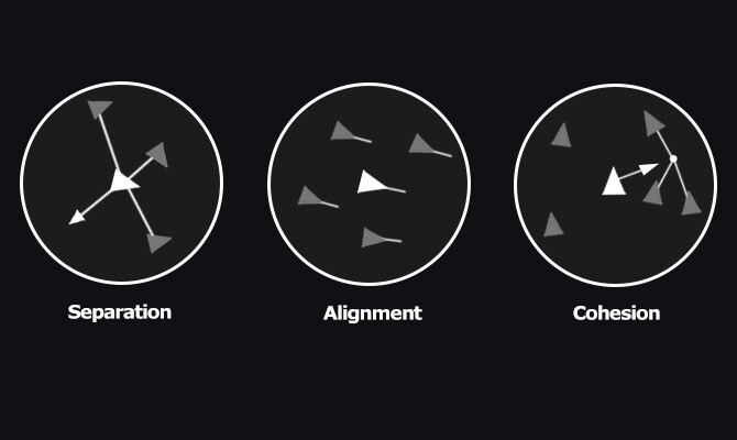
The term "Boids" is a play on the words "bird-oid objects" and refers to the entities within the simulation. The algorithm's primary focus is on three key behaviours: separation, alignment, and cohesion.
- Separation: Each Boid aims to maintain a safe distance from its neighbouring Boids, avoiding collisions and overcrowding.
- Alignment: Boids attempt to match the average direction and speed of nearby Boids, resulting in collective alignment of movement.
- Cohesion: Boids strive to move towards the center of mass of nearby Boids, promoting group cohesion.
Controlling these individual elements enables us to program the flock movement.
Sample implementation elements
The sample implementation will consist of these elements:
CS_Boids.cs: This script oversees the execution of the compute shader (dispatching) and is accountable for simulating boids.
CS_Boids.compute: A compute shader that executes calculations required for boids simulation.
CS_BoidsRender.cs: This script responsible for custom approach to render each boid visual element.
S_Boid.hlsl: A shader to be used for Boids rendering.
CS_Boids.cs
Let's start with adding variables and elements that will describe & control boid behaviour.
First, we need a struct that will hold (per boid) velocity and position data
[System.Serializable]
struct BoidData
{
    public Vector3 velocity;
    public Vector3 position;
}
Next, add a property to control the total amount of boids to be rendered/simulated.
Range(128, 60000)]
[SerializeField] private int boidsCount = 5000;
Earlier, we introduced components tasked with simulating behaviors (Cohesion, Alignment, Separation, abbreviated as CAS). Now, let's incorporate these attributes:
[Header("CAS Radius")]
[SerializeField] private float cohesionRadius = 1.0f; // Radius for applying cohesion to other individuals
[SerializeField] private float alignmentRadius = 1.0f; // Radius for applying alignment to other individuals
[SerializeField] private float separationRadius = 0.5f; // Radius for applying separation to other individuals

[Header("CAS Forces")]
[SerializeField] private float cohesionWeight = 0.5f; // Cohesion force appliance weight
[SerializeField] private float alignmentWeight = 0.5f; // Alignment force appliance weight
[SerializeField] private float separationWeight = 2.0f; // Separation force appliance weight
For boids themselves, two additional properties required: Maximum Speed and Maximum Steering Force.
[Header("Boid")]
[SerializeField] private float boidMaximumSpeed = 10.0f; // Boid maximum speed
[SerializeField] private float boidMaxSteeringForce = 1.0f; // Boid maximum steering force
Simulation itself should have certain properties to be defined. These include: Simulation Center, Dimensions (X, Y, Z bounds), and Bounds Avoidance Weight.
[Header("Simulation")]
[SerializeField] private Vector3 simulationCenter = Vector3.zero; // Simulation center
[SerializeField] private Vector3 simulationDimensions = new Vector3(32.0f, 32.0f, 32.0f); // Simulation dimensions
[SerializeField] private float simulationBoundsAvoidWeight = 10.0f; // Bounding avoidance weight
To store data that should be passed between CPU <--> GPU, we need two Compute Buffers.
private ComputeBuffer _boidsSteeringForcesBuffer; // Buffer for Boids steering forces values storage
private ComputeBuffer _boidsDataBuffer; // Buffer storing basic data of Boids (velocity, position, Transform, etc.)


Furthermore, a number of private properties are necessary to retain cached data:
private uint _storedThreadGroupSize; // Thread group size received from Compute Shader
private int _dispatchedThreadGroupSize; // Thread group size calculated

private int _steeringForcesKernelId; // Kernel for processing boids steering forces calculation
private int _boidsDataKernelId; // Kernel for processing boids steering forces calculation
Now, moving on to the practical aspect. Let's begin with the initialization functions aimed at preparing data associated with buffers and Compute Shader kernels.
private void Start()
{
    InitBuffer();
    InitKernels();
}
Buffers initialization.
private void InitBuffers()
{
    _boidsDataBuffer = new ComputeBuffer(boidsCount, sizeof(float) * 6); // 6 for two Vector3
    _boidsSteeringForcesBuffer = new ComputeBuffer(boidsCount, sizeof(float) * 3); // 3 for one Vector3

    // Prepare data arrays
    Vector3[] forceArr = new Vector3[boidsCount];
    BoidData[] boidDataArr = new BoidData[boidsCount];

    for (var i = 0; i < boidsCount; i++)
    {
        forceArr[i] = Vector3.zero;
        boidDataArr[i].position = Random.insideUnitSphere * 1.0f;
        boidDataArr[i].velocity = Random.insideUnitSphere * 0.1f;
    }

    // Set data to buffers
    _boidsSteeringForcesBuffer.SetData(forceArr);
    _boidsDataBuffer.SetData(boidDataArr);
}
Kernels initialization. Here we are also making sure that correct amount of threads should be used (so no "unprocessed" elements will be rendered).
private void InitKernels()
{
    _steeringForcesKernelId = boidsComputeShader.FindKernel("SteeringForcesCS");
    _boidsDataKernelId = boidsComputeShader.FindKernel("BoidsDataCS");

    boidsComputeShader.GetKernelThreadGroupSizes(_steeringForcesKernelId, out _storedThreadGroupSize, out _, out _);
    var dispatchedThreadGroupSize = boidsCount / (int)_storedThreadGroupSize;

    if (dispatchedThreadGroupSize % _storedThreadGroupSize == 0) return;

    while (dispatchedThreadGroupSize % _storedThreadGroupSize != 0)
    {
        dispatchedThreadGroupSize += 1;
        if (dispatchedThreadGroupSize % _storedThreadGroupSize != 0) continue;

        _dispatchedThreadGroupSize = dispatchedThreadGroupSize;

        Debug.LogFormat("Initial threads: {0}", _storedThreadGroupSize);
        Debug.LogFormat("Threads X used: {0}", _dispatchedThreadGroupSize);
        break;
    }
}
As CS_Boids script will be referenced and used by other resources (mentioned earlier), let's add several public accessors for convenient data usage.
public ComputeBuffer GetBoidsData()
{
    return _boidsDataBuffer;
}

public int GetBoidsCount()
{
    return boidsCount;
}

public Vector3 GetSimulationCenter()
{
    return simulationCenter;
}

public Vector3 GetSimulationDimensions()
{
    return simulationDimensions;
}
Now we need a method that will process data between CPU <--> GPU and actually execute compute shader's kernels.
private void Update()
{
    Simulation(_steeringForcesKernelId, _boidsDataKernelId);
}
private void Simulation(int steeringForcesKernelId, int boidsDataKernelId)
{
    if(boidsComputeShader == null) return;

    boidsComputeShader.SetInt("_BoidsCount", boidsCount);

    boidsComputeShader.SetBuffer(steeringForcesKernelId, "_BoidsDataBuffer", _boidsDataBuffer);
    boidsComputeShader.SetBuffer(steeringForcesKernelId, "_BoidsSteeringForcesBufferRw", _boidsSteeringForcesBuffer);
    boidsComputeShader.SetBuffer(boidsDataKernelId, "_BoidsSteeringForcesBuffer", _boidsSteeringForcesBuffer);
    boidsComputeShader.SetBuffer(boidsDataKernelId, "_BoidsDataBufferRw", _boidsDataBuffer);

    boidsComputeShader.SetFloat("_CohesionRadius", cohesionRadius);
    boidsComputeShader.SetFloat("_AlignmentRadius", alignmentRadius);
    boidsComputeShader.SetFloat("_SeparationRadius", separationRadius);
    boidsComputeShader.SetFloat("_BoidMaximumSpeed", boidMaximumSpeed);
    boidsComputeShader.SetFloat("_BoidMaximumSteeringForce", boidMaxSteeringForce);
    boidsComputeShader.SetFloat("_SeparationWeight", separationWeight);
    boidsComputeShader.SetFloat("_CohesionWeight", cohesionWeight);
    boidsComputeShader.SetFloat("_AlignmentWeight", alignmentWeight);
    boidsComputeShader.SetFloat("_SimulationBoundsAvoidWeight", simulationBoundsAvoidWeight);

    boidsComputeShader.SetVector("_SimulationCenter", simulationCenter);
    boidsComputeShader.SetVector("_SimulationDimensions", simulationDimensions);

    boidsComputeShader.SetFloat("_DeltaTime", Time.deltaTime);

    boidsComputeShader.Dispatch(steeringForcesKernelId, _dispatchedThreadGroupSize, 1, 1);
    boidsComputeShader.Dispatch(boidsDataKernelId, _dispatchedThreadGroupSize, 1, 1);
}
Remember to ensure proper cleanup of the created buffer and its associated memory when the application is not running.
private void OnDestroy()
{
    ReleaseBuffer();
}
private void ReleaseBuffer()
{
    SafeReleaseBuffer(ref _boidsDataBuffer);
    SafeReleaseBuffer(ref _boidsSteeringForcesBuffer);
}
private void SafeReleaseBuffer(ref ComputeBuffer buffer)
{
if (buffer == null) return;
buffer.Release();
buffer = null;
}Now check the inspector, it should look something like this. And now we can proceed to compute shader's code (CS_Boids.compute).

CS_Boids.compute
There are two kernels that we will use for CS_Boids compute shader. One is responsible for calculating (accumulating) steering forces, produced by Cohesion, Separation, Alignment. Second kernel is used for applying that force and update boids velocity values and positions as a result.
#pragma kernel SteeringForcesCS
#pragma kernel BoidsDataCS
Next, add the BoidData struct that will hold the information about each boid, including its velocity and position in 3D space.
struct BoidData
{
   float3 velocity;
   float3 position;
};
Next, we will need a constant, that determines the number of threads in each thread group. Utilize the HLSL #define directive to establish the thread group size, ensuring that we only need to modify this value once instead of multiple times within the shader's code.
#define THREAD_GROUP_SIZE 128
In order to process boids data, create several structured buffers
// Boids read-only structured buffer
StructuredBuffer<BoidData> _BoidsDataBuffer;

// Boids read-write structured buffer
RWStructuredBuffer<BoidData> _BoidsDataBufferRw;

// Boids steering forces buffer
StructuredBuffer<float3> _BoidsSteeringForcesBuffer;

// Read-write boids steering forces buffer
RWStructuredBuffer<float3> _BoidsSteeringForcesBufferRw;
Declare this set of parameters, that will represent boids-related data.
int _BoidsCount; // Total boids count

float _DeltaTime;      // Time elapsed since the previous frame

float _SeparationRadius; // Radius for applying separation to other individuals
float _AlignmentRadius; // Radius for applying alignment to other individuals
float _CohesionRadius;  // Radius for applying cohesion to other individuals

float _BoidMaximumSpeed;
float _BoidMaximumSteeringForce;

float _SeparationWeight;  // Separation force appliance weight
float _AlignmentWeight; // Alignment force appliance weight
float _CohesionWeight;  // Cohesion force appliance weight

float4 _SimulationCenter;
float4 _SimulationDimensions;
float _SimulationBoundsAvoidWeight;
Next, we will need two utility functions.
• Limit() function limits the magnitude of a given 3D vector to a specified maximum value. It calculates the squared length of the vector and compares it with the square of the maximum value. If the squared length is greater than the squared maximum value and is also greater than zero, it calculates the magnitude of the vector, scales it down to the specified maximum, and returns the scaled vector. Otherwise, it returns the original vector.
float3 limit(float3 vec, float max)
{
   float lengthSquared = dot(vec, vec);

   if (lengthSquared > max * max && lengthSquared > 0)
   {
      float length = sqrt(lengthSquared); // magnitude
      return vec.xyz * (max / length);
   }
   return vec.xyz;
}
• CheckSimulationBounds() function is responsible for handling the behavior of a boid upon reaching the simulation boundaries.
float3 CheckSimulationBounds(float3 position)
{
   float3 wc = _SimulationCenter.xyz;
   float3 ws = _SimulationDimensions.xyz;

   float3 acc = float3(0, 0, 0);

   acc.x = (position.x < wc.x - ws.x * 0.5) ? 1.0 : ((position.x > wc.x + ws.x * 0.5) ? -1.0 : 0.0);
   acc.y = (position.y < wc.y - ws.y * 0.5) ? 1.0 : ((position.y > wc.y + ws.y * 0.5) ? -1.0 : 0.0);
   acc.z = (position.z < wc.z - ws.z * 0.5) ? 1.0 : ((position.z > wc.z + ws.z * 0.5) ? -1.0 : 0.0);


   return acc;
}
To proceed with compute shader code review, we need to introduce an interesting concept called Shared Memory Array.
Shared memory is a small, fast-access memory space that is shared among threads within a single thread group. It is physically located on the GPU chip and is much faster to access compared to global memory, which is off-chip. Shared memory is used to hold frequently accessed data that needs to be shared among threads within the same group. We barrely touched this concept in Compute Shaders in Unity: Shader Core Elements, First Compute Shader Review article.
Incorporate the following code, which establishes a shared memory array referred to as "boid_data." This array serves as a storage unit for boid-related information within the thread group. This utilization of shared memory is a crucial optimization strategy in GPU programming, designed to improve memory access patterns and reduce data retrieval delays.
groupshared BoidData boid_data[THREAD_GROUP_SIZE];
Back to compute shader code.
SteeringForcesCS kernel calculates the steering forces acting on each boid based on separation, alignment, and cohesion. It iterates over all boids and computes the forces acting on the current boid due to nearby boids within specified radius. The calculated forces are adjusted, normalized, and limited as required. The resulting forces are accumulated to produce the final steering force applied to the boid.
[numthreads(THREAD_GROUP_SIZE, 1, 1)]
void SteeringForcesCS (
   uint3 d_tid : SV_DispatchThreadID, // thread group unique ID
   uint  gi : SV_GroupIndex          // One-dimensional version of SV_GroupThreadID ranging from 0 to 255
)
{
   const unsigned int P_ID = d_tid.x; // Self ID
   const float3 P_position = _BoidsDataBuffer[P_ID].position; // Self position
   const float3 P_velocity = _BoidsDataBuffer[P_ID].velocity; // Self velocity

   //Resulting steering force
   float3 force = float3(0, 0, 0);

   //Position offsets influenced by cohesion, alignment, and separation
   float3 separationPositionOffset = float3(0, 0, 0);
   float3 alignmentPositionOffset = float3(0, 0, 0);
   float3 cohesionPositionOffset = float3(0, 0, 0);

   //Cumulative count of boids that need to be influenced by cohesion, alignment, and separation
   int separationBoidsCount = 0;
   int alignmentBoidsCount = 0;
   int cohesionBoidsCount = 0;

   //Accumulated steering forces
   float3 separationSteering = float3(0, 0, 0);
   float3 alignmentSteering = float3(0, 0, 0);
   float3 cohesionSteering = float3(0, 0, 0);

   // Loop unrolling
    [loop]
    for (uint n_block_id = 0; n_block_id < (uint)_BoidsCount; n_block_id += THREAD_GROUP_SIZE)
    {
        boid_data[gi] = _BoidsDataBuffer[n_block_id + gi];
        GroupMemoryBarrierWithGroupSync();


        // Conditional execution and memory coalescing
        [unroll]
        for (int N_tile_ID = 0; N_tile_ID < THREAD_GROUP_SIZE; N_tile_ID++)
        {
           const float3 N_position = boid_data[N_tile_ID].position;
           const float3 N_velocity = boid_data[N_tile_ID].velocity;


            const float3 diff = P_position - N_position; // position difference between current and other boids
            const float dist = sqrt(dot(diff, diff)); // distance difference between current and other boids


           //Separation
            if (dist > 0.0 && dist <= _SeparationRadius)
            {
                float3 repulse = normalize(P_position - N_position);
                repulse /= dist;
                separationPositionOffset += repulse;
                separationBoidsCount++;
            }


           //Alignment
            if (dist > 0.0 && dist <= _AlignmentRadius)
            {
                alignmentPositionOffset += N_velocity;
                alignmentBoidsCount++;
            }


           //Cohesion
            if (dist > 0.0 && dist <= _CohesionRadius)
            {
                cohesionPositionOffset += N_position;
                cohesionBoidsCount++;
            }
        }

        GroupMemoryBarrierWithGroupSync();
    }

   if (separationBoidsCount > 0)
   {
      separationSteering = separationPositionOffset / (float)separationBoidsCount;     // Calculate the average
      separationSteering = normalize(separationSteering) * _BoidMaximumSpeed; // Adjust to maximum speed
      separationSteering = separationSteering - P_velocity;           // Calculate steering force
      separationSteering = limit(separationSteering, _BoidMaximumSteeringForce); // Limit the steering force
   }

   if (alignmentBoidsCount > 0)
   {
      alignmentSteering = alignmentPositionOffset / (float)alignmentBoidsCount;
      alignmentSteering = normalize(alignmentSteering) * _BoidMaximumSpeed;
      alignmentSteering = alignmentSteering - P_velocity;
      alignmentSteering = limit(alignmentSteering, _BoidMaximumSteeringForce);
   }

   if (cohesionBoidsCount > 0)
   {
      cohesionPositionOffset = cohesionPositionOffset / (float)cohesionBoidsCount;
      cohesionSteering = cohesionPositionOffset - P_position;
      cohesionSteering = normalize(cohesionSteering) * _BoidMaximumSpeed;
      cohesionSteering = cohesionSteering - P_velocity;
      cohesionSteering = limit(cohesionSteering, _BoidMaximumSteeringForce);
   }

   //Pass accumulated steering forces to resulting value
   force += alignmentSteering * _AlignmentWeight;
   force += cohesionSteering * _CohesionWeight;
   force += separationSteering * _SeparationWeight;

   _BoidsSteeringForcesBufferRw[P_ID] = force;
}
In addition to the computations that result in the accumulation of steering forces, there are two additional aspects to highlight.
• Loop unrolling is an optimization technique where a loop is manually expanded or unwound into multiple iterations. This reduces the overhead of loop control and improves memory access patterns, potentially leading to better parallelism and performance. In other words, instead of having a loop that iterates through a range of values, you manually write out the loop's body multiple times. The concept of loop unrolling is implemented with [loop] and [unroll] directives.
• GroupMemoryBarrierWithGroupSync() method is a synchronization mechanism used in HLSL (High-Level Shading Language) within compute shaders to ensure proper memory visibility and synchronization between threads within a thread group.
Here's a simplified flow of how GroupMemoryBarrierWithGroupSync() works:
- Threads within a thread group execute code.
- Before a GroupMemoryBarrierWithGroupSync() is encountered, threads perform memory reads and writes.
- Threads reach the barrier and pause execution.
- The barrier ensures that all previous memory operations are completed before allowing threads to proceed.
- Once all threads within the thread group reach the barrier, they can continue executing code.
BoidsDataCS kernel handles the updates to boid velocity and position based on the calculated steering forces. It reads the current boid data and the associated steering force from the buffers. It also applies a repelling force if the boid is approaching the simulation boundaries. The updated velocity and position are calculated and written back to the buffer.
[numthreads(THREAD_GROUP_SIZE, 1, 1)]
void BoidsDataCS(uint3 DTid : SV_DispatchThreadID) // Thread-wide unique ID
{
   const unsigned int p_id = DTid.x;          // Self ID

   BoidData boidData = _BoidsDataBufferRw[p_id];   // Read current Boid data
   float3 force = _BoidsSteeringForcesBuffer[p_id]; // Read steering force

   // Apply repelling force when approaching simulation bounds
   force += CheckSimulationBounds(boidData.position) * _SimulationBoundsAvoidWeight;

   boidData.velocity += force * _DeltaTime;          // Apply steering force to velocity
   boidData.velocity = limit(boidData.velocity, _BoidMaximumSpeed); // Limit velocity
   boidData.position += boidData.velocity * _DeltaTime;     // Update position

   _BoidsDataBufferRw[p_id] = boidData;            // Write calculation result
}
CS_BoidsRender.cs
This script is responsible for rendering boid entities using GPU instancing. It works in conjunction with the CS_Boids script, which manages the boid simulation.
First, let's add several properties:
- csBoids (SerializeField): A reference to the CS_Boids script component responsible for managing boid simulation data.
[SerializeField] private CS_Boids csBoids;
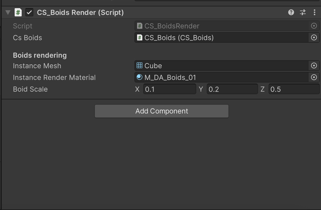
- boidScale (SerializeField): A vector representing the scale of the rendered boid objects.
- instanceMesh (SerializeField): A reference to the mesh that will be instanced for rendering.
- instanceRenderMaterial (SerializeField): A reference to the material used for rendering the instanced boid objects.
[SerializeField] private Mesh instanceMesh;
[SerializeField] private Material instanceRenderMaterial;
[SerializeField] public Vector3 boidScale = new Vector3(0.2f, 0.3f, 0.6f);
- _supportsInstancing: A boolean indicating whether the hardware supports GPU instancing.
- _instanceMeshIndexCount: The number of indices in the mesh being instanced.
- _boidsCount: The total number of boids in the simulation.
private bool _supportsInstancing;
private uint _instanceMeshIndexCount;
private uint _boidsCount;
- _simulationBounds: A bounding area defining the spatial extent of the simulation.
private Bounds _simulationBounds;
- _args: An array of arguments used for GPU instancing. These include indices per instance, instance count, start index location, base vertex location, and start instance location.
private readonly uint[] _args = new uint[5] { 0, 0, 0, 0, 0 };
- _argsBuffer: A ComputeBuffer used for transferring the _args data to the GPU.
private ComputeBuffer _argsBuffer;
- BoidDataBuffer (static readonly): The shader property ID for the boid data buffer.
- Scale (static readonly): The shader property ID for the object scale.
private static readonly int BoidDataBuffer = Shader.PropertyToID("_BoidDataBuffer");
private static readonly int Scale = Shader.PropertyToID("_BoidScale");
Save the C# script and check the inspector. Picture should be similar to this one.
Awake() method retrieves the CS_Boids script component when the script is initialized.
private void Awake()
{
    csBoids = GetComponent<CS_Boids>();
}
In Start() we initialize various values, such as checking for GPU instancing support, obtaining the mesh's index count, and getting the total boids count from the CS_Boids script.
private void Start()
{
    InitValues();
    GetSimulationBounds();
}
InitValues() method initializes values required for rendering, including GPU instancing support, mesh index count, and boids count. It also creates the _argsBuffer for GPU instancing arguments.
private void InitValues()
{
    _supportsInstancing = SystemInfo.supportsInstancing;
    _instanceMeshIndexCount = (instanceMesh != null ? instanceMesh.GetIndexCount(0) : 0);
    _boidsCount = (uint)csBoids.GetBoidsCount();

    _argsBuffer = new ComputeBuffer(1, _args.Length * sizeof(uint),
        ComputeBufferType.IndirectArguments);
}
In Update() method we need to check whether conditions are met for rendering, and if so, calls the RenderInstancedMesh() method.
private void Update()
{
    if (instanceRenderMaterial == null || csBoids == null || !_supportsInstancing)
        return;

   RenderInstancedMesh();
}
Keep in mind to release the _argsBuffer when the script is disabled or destroyed.
private void OnDisable()
{
    _argsBuffer?.Release();
}
RenderInstancedMesh() method is used to render the instanced mesh using GPU instancing. It updates the _args buffer, creates a MaterialPropertyBlock for shader properties, and draws the instanced mesh using GPU instancing and the provided material.
private void RenderInstancedMesh()
{
    // Update the arguments buffer
    _args[0] = _instanceMeshIndexCount;
    _args[1] = _boidsCount;
    _argsBuffer.SetData(_args);

    // Create a MaterialPropertyBlock
    var propertyBlock = new MaterialPropertyBlock();

    // Set the boid data buffer and scale property in the property block
    propertyBlock.SetBuffer(BoidDataBuffer, csBoids.GetBoidsData());
    propertyBlock.SetVector(Scale, boidScale);

    // Draw the mesh using GPU instancing with the property block
    Graphics.DrawMeshInstancedIndirect(instanceMesh, 0, instanceRenderMaterial, _simulationBounds, _argsBuffer, 0, propertyBlock);
}
With GetSimulationBounds() we can get simualtion bounds data.
private void GetSimulationBounds()
{
    // Define the bounding area
    _simulationBounds = new Bounds
    (
        csBoids.GetSimulationCenter(),
        csBoids.GetSimulationDimensions()
    );
}
S_Boid.hlsl
S_Boid shader is used for rendering dynamic boids instances using GPU instancing. The particular shader is designed to render the boids based on their positions, velocities, and other properties stored in a structured buffer.
Before adiving into code, we have to familiarize ourselves with concept of angles naming, used in this shader (Pitch, Roll, Yaw).
"Pitch," "Roll," and "Yaw" are terms used to describe the rotational movements of an object in three-dimensional space. These terms are commonly used in aviation, aerospace, robotics, and computer graphics to define the orientation of an object or vehicle. In relation to XYZ coordinates:
- Pitch - X coordinate
- Roll - Y coordinate
- Yaw - Z coordinate

Shifting our focus to the coding aspect...
Create a new Unlit shader as it already includes all fundamental shader code. Now, let's modifiy it.
Add instancing_options #pragma. It indicates that GPU instancing will be used with procedural setup.
#pragma instancing_options procedural: setup
We also need a special struct named BoidData. It contains the per-instance data for each "Boid," including velocity and position. Define it after standard appdata and v2f structs.
struct BoidData
{
    half3 velocity;
    half3 position;
};
Next, define a structured buffer that holds the Boid data (velocity and position) for each instance.
StructuredBuffer<BoidData> _BoidDataBuffer;
A uniform variable that holds the scale of each Boid instance.
half3 _BoidScale;
You've noticed that there's a new precision is used (half). Its commonly used in situations where memory consumption and performance are important factors, such as mobile devices or (in our case) massive objects simulations.
When choosing between half and float in HLSL shaders, you need to consider the trade-off between precision and performance. If your shader requires high precision and you're not constrained by memory or processing power, you might opt for float. On the other hand, if memory efficiency and performance are critical, half could be a better choice. It's important to note that not all GPUs support half natively, so the level of hardware support can also influence your decision.
In order to get a 4x4 rotation matrix, let's create a utility function named eulerToMatrix(float3 inputAngles). It would be a function that calculates a rotation matrix from Euler angles (yaw, pitch, roll) and returns it.
half4x4 eulerToMatrix(float3 inputAngles)
{
       // Calculate sine and cosine values for each angle
 half cosYaw = cos(inputAngles.y);
 half sinYaw = sin(inputAngles.y);
 half cosPitch = cos(inputAngles.x);
 half sinPitch = sin(inputAngles.x);
 half cosRoll = cos(inputAngles.z);
 half sinRoll = sin(inputAngles.z);

 // Create a 4x4 rotation matrix to hold the result
 // Fill in the rotation matrix elements using the calculated values
 // Yaw-Pitch-Roll (Ry-Rx-Rz)
 return half4x4(
     cosYaw * cosRoll + sinYaw * sinPitch * sinRoll, -cosYaw * sinRoll + sinYaw * sinPitch * cosRoll, sinYaw * cosPitch, 0,
     cosPitch * sinRoll, cosPitch * cosRoll, -sinPitch, 0,
     -sinYaw * cosRoll + cosYaw * sinPitch * sinRoll, sinYaw * sinRoll + cosYaw * sinPitch * cosRoll, cosYaw * cosPitch, 0,
     0, 0, 0, 1
 );  // float4(0, 0, 0, 1) for homogeneous coordinates in the last row
}
The vertex shader processes each instance's vertex data and transforms it.
- It retrieves Boid data (position, velocity) using the instance ID.
- Extracts the position and scale values of the current instance.
- Calculates rotation angles based on the velocity components (yaw and pitch).
- Computes a rotation matrix using the calculated angles.
- Combines the rotation and scale in a single matrix and applies translation.
- Transforms the vertex position using the combined matrix.
- Passes the transformed vertex position and UV coordinates to the fragment shader.
Code follows:
v2f vert (appdata v)
        {
            v2f o;

            BoidData boidData = _BoidDataBuffer[v.unity_InstanceID];

            float3 pos = boidData.position.xyz;
   half3 boidScale = _BoidScale;

float4x4 object2world = 0;

// Assign the scale value
object2world._11_22_33_44 = float4(boidScale.xyz, 1.0);

// Calculate the rotation around the Y-axis from the velocity
half rotY =
   atan2(boidData.velocity.x, boidData.velocity.z);

// Calculate the rotation around the X-axis from the velocity
half rotX =
   -asin(boidData.velocity.y / (length(boidData.velocity.xyz) + 1e-8));

// Calculate the rotation matrix from Euler angles (in radians)
half4x4 rotMatrix = eulerToMatrix(half3(rotX, rotY, 0));


           // Apply rotation to the matrix
object2world = mul(rotMatrix, object2world);

// Apply translation to the matrix
object2world._14_24_34 += pos.xyz;

v.vertex = mul(object2world, v.vertex);
           o.vertex = UnityObjectToClipPos(v.vertex);
            o.uv = TRANSFORM_TEX(v.uv, _MainTex);

            return o;
        }
The fragment shader simply samples the main texture using UV coordinates and returns the resulting color.
half4 frag (v2f i) : SV_Target
{
    half4 col = tex2D(_MainTex, i.uv);
    return col;
}
There might be a specific confusion surrounding values like object2world._14_24_34. Let's comprehensively break it down now.
In our scenario, we're assigning values to matrices for transformation, rotation, and scaling.
- Translation matrix is used to move or position objects in three-dimensional space. A translation matrix is usually represented as a 4x4 matrix, known as a homogeneous transformation matrix. This matrix includes elements that correspond to the X, Y, and Z translations, as well as a fourth row used for perspective transformations.
- Rotation matrix is a 3x3 or 4x4 matrix that is used to represent the orientation of an object in three-dimensional space. Its designed to perform rotations around one or more coordinate axes, such as the X, Y, and Z axes. It is constructed based on trigonometric functions like sine and cosine to encode the rotation angles. A 3x3 rotation matrix is generally used for rotations in three-dimensional space, while a 4x4 matrix can also include translation and scaling transformations in addition to rotation.
- Scale matrix is a diagonal matrix used to uniformly scale objects in three-dimensional space. Scale matrices are often represented as 3x3 or 4x4 matrices and defined by the scaling factors applied along the X, Y, and Z axes. When a vector is multiplied by a scale matrix, its individual components are multiplied by the corresponding scaling factors. This results in uniformly changing the size of an object while maintaining its proportions.

Concerning these seemingly unusual numbers like _14_24_34, they correspond to specific components within the matrix. 14, 24, 34 stands for particular component address.
Please review this picture to visually understand the labeling/addressing/positioning of each element within the matrix (General matrix components arrangement).
The elements tX, tY, and tZ correspond to the X, Y, and Z coordinates, respectively (Translation matrix).
Similarly, the components sX, sY, and sZ correspond to the X, Y, and Z coordinates (Scaling matrix).
A rotation matrix is designed to perform rotations around one or more coordinate axes, such as the X, Y, and Z axes. Speaking of setting components' values:
Once the rotation matrix is established, you can apply it to vertices or vectors to achieve the desired rotation effect.
Whew, now we're all set to bring everything together and check out the resulting outcome (and of course, play around with values and visuals).

Congratulations! You've done it! Boids movement powered by GPU capabilities.
Thanks a lot for attention, and until the next time!
Support Decompiled Art on Patreon
(and get source files for this article)

***
FOLLOW AND CHECK FOR UPDATES:
Decompiled Art YouTube
Decompiled Art Instagram
Decompiled Art Twitter
Decompiled Art Facebook
***