This article is designed as a practical and readable guide to every vertex attribute in Unity. Particularly, what they are, how they’re stored in memory, how shaders access them, and how you can add your own for fast, efficient vertex operations.
We’ll be working in Unity 6.0+ with URP 17+, using them as both the primer and the playground.
My overall intention is that, by the end, you’ll have a clear understanding of what lives inside a mesh, how that data makes its way into your shaders, which “places” are best for custom attributes, and how to deform geometry at the vertex stage without stalls, seams, or unexpected behavior.
Let’s dive in!
---
Contents:
- From DCC (authoring application) to Vertex Shader - The Big Picture
- Vertex Attributes. What They Are and Why They Matter
- A typical GPU-friendly data layout
- Detailed attributes breakdown
- Position
- Example: per-vertex position transforms
- Normal
- Example: normals processing and transforms
- Tangent
- Example: TBN matrix build-up
- UV Sets
- Standard UV Sets
- Efficient Usage: half vs float
- Example: Base and Lightmap UVs
- Custom Data in UV Channels
- Example: uv2 channel usage
- Conventions you might find useful in your pipelines
- Vertex Color
- Sample channels usage scenario
- Example: Sampling Specific Vertex Color Data
- Example: Using Vertex Colors Instead of Textures
- Skin weights and indices
- Recommended practices
- Blend Shapes
- Example: Blend Shapes deltas sampling within shader
- Position
- Data Packing & Precision
- Why precision matters
- Where half precision shines
- Example: data processing and demote (type cast)
- More samples of using half precision
- Where you should stick with float
- Per-Platform notes
- Where to Put Custom Data
- Additional vertex streams
- Structured/GraphicsBuffer
- GPU Instancing / SRP Batcher
- Example: GPU Instancing setup
- Example: SRP Batcher support implementation
- Vertex Deformation & Transforms within the Shader
- Example: Vertex deformation pattern
- Mesh attributes used by Renderer components in Unity
---
From DCC (authoring application) to Vertex Shader - The Big Picture
Think of a mesh as a spreadsheet the GPU can read very quickly. Each row is a vertex; each column is an attribute. A second file of tiny integers (your index buffer) tells the GPU which three rows make a triangle. Submeshes are just named slices through that index file. With this slice, different triangles can use different materials.
Processing a mesh involves several steps:

- Authoring App (Houdini, Blender, Maya, etc.). Artists define geometry, materials, and extra data (UVs, vertex colors, skin weights).
-
Mesh Data. A mesh is a structured collection of vertex and index buffers. Each vertex can store multiple attributes:
- position,
- normal,
- tangent,
- UV sets,
- vertex color,
- skin weights and indices,
- blend shapes.
These attributes define the geometry and visual behavior of the mesh, and later determine how it can be manipulated or deformed within shaders.
- Engine Import. CPU prepares mesh data, packs attributes efficiently, and sets up additional streams if needed. The engine reads the file and builds its internal mesh representation, optimizing data for the render pipeline (e.g., compression and precision adjustments).
- GPU Buffers. Vertex attributes are uploaded into GPU memory.
- Vertex Shader. The shader consumes attributes, transforms geometry, and can apply deformations using both built-in and custom data
When a draw happens, an engine streams one row (the current vertex) into your vertex function. The function transforms it from object space to clip space and sends only chosen values forward as varyings for the fragment stage. Be mindful of the varying amounts. If you allocate too much, you could end up overspending on certain platforms. This is why mesh layout and packing matter even if your math is simple.
The cost of moving data often dwarfs the cost of a few extra ALU instructions.
---
Vertex Attributes. What They Are and Why They Matter
A typical GPU-friendly data layout
Before we unpack each attribute, it helps to have a mental target. The layout below prioritizes bandwidth and cache friendliness without sacrificing the data shaders need for lighting and deforms. It also maps cleanly to Unity/URP semantics.
Unity attributes layout for a default quad looks like that:
position              : float32 x 3       // 12 bytes (3 × 4)
normal       : float32 x 3    //  12 bytes (3 × 4)
tangent (+sign)       : float32 x 4 //  16 bytes (4 x 4)
uv0                   : float32 x 2         //  8 bytes (4 x 2)
uv1 (lightmap)        : float32 x 2 //  8 bytes (4 x 2)
----------------------------------------------------
Total per-vertex                       56 bytes
To summarize, positions stay full-precision, normal and tangent vectors are compact but stable. UVs/colors use half/unorm where range is small.
And if skinned meshes data is present:
+ boneIndices : uint32 x 4 // 16 bytes (4 x 4)
+ boneWeights         : float32 x 4 //  16 bytes (4 x 4)
----------------------------------------------------
Total per-vertex 88 bytes

Important note:
If you leave Unity’s defaults, bone weights may arrive as float4 (16 bytes). Switching to unorm8x4 plus normalization in the shader saves 12 bytes/vertex with no visible loss for typical rigs.
But how this data is represented within Unity shader? Let's take a look:
struct Attributes
{
    float3 positionOS : POSITION;
    float3 normalOS   : NORMAL; // Packed snorm 10:10:10:2 is expanded to float3 by Unity; you can effectively decode it yourself
    float4 tangentOS  : TANGENT;   // xyz = tangent, w = bitangent sign (±1)
    half2  uv0        : TEXCOORD0; // base textures
    half2  uv1        : TEXCOORD1; // lightmap/GI
    half4  color      : COLOR;     // unorm8x4 -> 0..1
    uint4  boneIndex  : BLENDINDICES0; // skinned only (u8x4)
    half4  boneWeight : BLENDWEIGHT0;  // skinned only (unorm8x4 -> 0..1)
};
---
Detailed attributes breakdown
Position
Represents the location of the vertex. Positions are stored in object space: coordinates relative to the mesh’s local origin. Most pipelines keep them as three 32-bit floats, though it’s common to quantize to 16-bit plus a scale/offset when building custom formats.
In the vertex shader, positions are usually deformed in object space, then transformed to world and clip space. If you bend a mesh, make sure normals and tangents follow the deformation; otherwise, lighting will appear incorrect (“sliding highlights”).

Example: per-vertex position transforms
float3 posOS = IN.positionOS;    // object space
float3 posWS = TransformObjectToWorld(posOS); // world space
OUT.positionCS = TransformWorldToHClip(posWS); // homogeneous clip space
Important note:
Saying a vertex is in “clip space” can be a bit misleading. After the vertex shader applies the projection matrix, the coordinates are actually in homogeneous clip space. It`s a 4D space (x, y, z, w) before the GPU performs the perspective divide. Only after dividing by w do we get Normalized Device Coordinates (NDC), which are the 3D coordinates the GPU uses for rasterization.
Normal
Represents the direction the vertex/surface faces. It`s a unit vector perpendicular to the surface, used by lighting models (e.g., Lambert, GGX) to determine how bright a point should appear.
Common storage options:
- Three floats: simple but bandwidth-heavy.
- Octahedral encoding: 2 components (8 or 16 bits) reconstruct a 3D unit vector.
- 10:10:10:2 packed snorm: packs a 3D vector plus sign into a single 32-bit value.

Example: normals processing and transforms
float3 normalOS = normalize(IN.normalOS); // normalized surface (object-space) normal
float3 normalWS = TransformObjectToWorldNormal(nOS); // transformed to world-space normals data
Important note:
Keep encoding consistent across passes and platforms, and renormalize after any transform or blending
Tangent
Represents how to orient a normal map. Normals alone aren’t enough to interpret a tangent-space normal map. To construct the TBN (Tangent, Bitangent, Normal) basis, you also need a tangent and bitangent orientation.

Example: TBN matrix build-up
float3x3 BuildTBN(float3 normal, float4 tangent)
{
    float3 N = normalize(normal);                    // unit‑length normal
    float3 T = normalize(tangent.xyz);               // unit‑length tangent
    float3 B = normalize(cross(N, T)) * tangent.w;   // unit‑length bitangent (handedness +1 or -1)
    return float3x3(T, B, N);                       // column‑major matrix: T, B, N
}
UV sets
UV sets are 2D coordinates used by shaders to sample textures. They are also excellent candidates for storing small per-vertex custom data.
Standard UV Sets
Most meshes include multiple UV sets:
- uv0 - drives base color, normal maps, and other standard textures,
- uv1 - typically reserved for lightmaps and baked GI. Keep this set clean: non-overlapping islands and proper padding are essential because lighting expects well-behaved UVs.
- uv2+ - optional extra UVs for decals, detail layers, triplanar weights, or per-vertex payloads like weights, masks, or scalars.
On the shader side UV arrive as float2, but it’s often safe to use them as half2 once you’re inside the shader. Many teams also quantize UVs to 16-bit at build time without visible loss, especially for non-hero assets.

Important note:
Always document repurposed UV channels: which component stores what, their ranges (0-1, signed, scaled), and which shader passes use them. This prevents hard-to-debug issues, especially in shadow or lightmap passes.
Efficient Usage: half vs float
- UVs data precision is float2 by default.
- Safe to demote (type cast) to half2: If you don’t perform heavy screen-space derivatives or large procedural calculations, converting to half2 halves the bandwidth cost with negligible visual difference.
- Keep float2: When UVs are used for custom filtering, screen-space derivatives or procedural coordinates where small quantization errors become noticeable.
Example: Base and Lightmap UVs
struct Attributes
{
    float2 uv0 : TEXCOORD0;   // Base textures
    float2 uv1 : TEXCOORD1;   // Lightmaps / baked GI
};

struct Varyings
{
    float4 positionCS : SV_POSITION;
    half2  uvBase     : TEXCOORD0;   // Demoted to half2 for bandwidth
    half2  uvLight    : TEXCOORD1;  // Lightmaps / baked GI
};

Varyings Vert(Attributes IN)
{
    Varyings OUT;

    // Transform, etc.
    ...

    OUT.uvBase  = (half2)IN.uv0;
    OUT.uvLight = (half2)IN.uv1;

    return OUT;
}

half4 Frag(Varyings IN) : SV_Target
{
    // Sample base texture
    half2 uv = IN.uvBase;
    float4 col_base = SAMPLE_TEXTURE2D(_BaseMap, sampler_BaseMap, uv);

    // Sample lightmap
    float2 lightmapUV = IN.uvLight * unity_LightmapST.xy + unity_LightmapST.zw;
    float3 bakedLight = SAMPLE_TEXTURE2D(unity_Lightmap, samplerunity_Lightmap, lightmapUV).rgb;

    // Combine lighting
    return albedo;
}
Custom Data in UV Channels
Extra UV sets (uv2+) can carry custom per-vertex data, such as detail layers, masks, or some kind of procedural weights.

Example: uv2 channel usage
struct Attributes
{
    float4 uv2 : TEXCOORD2;
    // Convention:
    // uv2.xy - detail UV (0..1 or tiled)
    // uv2.z  - wind weight (0..1)
    // uv2.w  - dissolve mask (0..1)
};

struct Varyings
{
    float4 positionCS : SV_POSITION;
    half2  uvDetail   : TEXCOORD2;  // Demoted to half2
    half   windW      : TEXCOORD3;
    half   dissolve   : TEXCOORD4;
};

Varyings Vert(Attributes IN)
{
    Varyings OUT;

    // Decode convention
    OUT.uvDetail = (half2)IN.uv2.xy;
    OUT.windW    = (half)saturate(IN.uv2.z);
    OUT.dissolve = (half)saturate(IN.uv2.w);

    // Example: wind pushes along normal
    // posOS += OUT.windW * _WindAmplitude * nOS;

    return OUT;
}
Conventions you might find useful in your pipelines
- xy - triplanar weights (the third weight is 1 - x - y), z - curvature or AO, w - blend factor for a decal/overlay.
- xy - world-space mapping anchor (projected UVs), z - vertex-painted wetness, w - per-vertex roughness tweak.
- xy - detail UV & zw - two packed 8-bit masks (if you quantize offline and unpack with zw / 255.0).
Vertex color
Vertex colors are four 8-bit channels (RGBA) that shaders expand to 0...1 floats. Provided in linear space, they can be treated like a numeric mask.
Art teams love them because they can be painted/edited directly via DCC and in-engine tools. Beyond coloring, vertex colors are perfect for storing custom data.
Sample channels usage scenario:
- R - Ambient occlusion
- G - Wetness factor
- B - Wind weight
- A - Effect mask (dissolve, push, emission, etc.)
In some textureless workflows, vertex colors can even be used as the primary color information instead of textures.
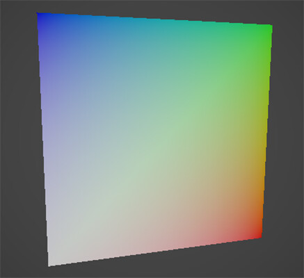
Example: Sampling Specific Vertex Color Data
struct Attributes
{
    float4 color : COLOR; // RGBA vertex color
};

struct Varyings
{
    float4 positionCS : SV_POSITION;
    half  ao         : TEXCOORD0; // R-channel, ambient occlusion
    half  wetness    : TEXCOORD1; // G-channel, wetness
    half  wind       : TEXCOORD2; // B-channel, wind weight
    half  effectMask : TEXCOORD3; // A-channel, custom effect
};

Varyings Vert(Attributes IN)
{
    Varyings OUT;

    // Example: direct sampling from vertex color
    OUT.ao         = (half)IN.color.r;
    OUT.wetness    = (half)IN.color.g;
    OUT.wind       = (half)IN.color.b;
    OUT.effectMask = (half)IN.color.a;

    // Transform position as usual
    // OUT.positionCS = TransformObjectToClip(...);

    return OUT;
}
Example: Using Vertex Colors Instead of Textures
half4 Frag(Varyings IN) : SV_Target
{
    // Combine vertex color channels into final color
    half3 col_base = half3(IN.ao, IN.wetness, IN.wind); // Example mapping
    half  mask_alpha  = IN.effectMask;

    return half4(col_base, mask_alpha);
}
Skin weights and indices
Skin weights and indices define how a vertex follows bones in a skinned mesh. Unity can import meshes with 1-to-32 bone influences per vertex, but real-time GPU skinning typically uses up to 4 influences to balance quality and performance.
At render time, the vertex’s final position is computed as a weighted sum of the bone matrices affecting it. More influences improve deformation quality, but also increase computational cost.
Recommended practices
- Limit GPU skinning to 4 bone influences per vertex for performance.
- Prune tiny weights (e.g., < 0.01) and renormalize to sum to 1
- Higher bone counts work well for offline baking or cinematics, while lower counts are better suited for real-time processing
- Reducing influences per vertex allows more skinnedMesh-driven entities to be drawn efficiently

Blend shapes
Blend shapes (or morph targets) store pre-authored per-vertex deltas, usually for positions and sometimes for normals or tangents. They allow meshes to deform dynamically at runtime.
By default, Unity’s SkinnedMeshRenderer applies blend shapes on the CPU. For better performance, you can move this work to the GPU using vertex animation textures (VAT) or a StructuredBuffer, applying the deltas directly in the vertex shader.
Important note:
If you push shapes far, expand your bounds or risk popping from frustum culling.

Example: Blend Shapes deltas sampling within shader
float3 posOS = IN.positionOS;
float3 deltaPos = BlendShapeDeltas[shapeIndex][vertexID]; // from StructuredBuffer
posOS += deltaPos * shapeWeight;                          // apply weighted delta
OUT.positionCS = TransformObjectToClip(posOS);
---
Data Packing & Precision
Efficient mesh and shader workflows are all about moving as little data as possible and maintaining just enough precision for your calculations. Choosing the right precision (half vs float, uint, etc.) helps reduce bandwidth, register usage, and memory while controlling numerical error.
If you can avoid moving or modifying a byte, do so. At the end, precision is part of the discipline.
Why precision matters
On many desktop GPUs, half promotes to 32-bit internally, so it mainly reduces bandwidth/register pressure, not ALU accuracy. On mobile/tile-based GPUs, half is often true 16-bit: you get real bandwidth savings, and you must respect its range (≈ ±65,504) and ~10-bit mantissa (about 3–3.5 decimal digits of precision). Either way, smaller payloads and fewer/lighter interpolators help.
Where half precision shines
Use half when values are local, low-dynamic-range, and not summed many times:
- UVs and masks: half2 is ideal for uv0..uvN, splat weights, blend factors, wind weights, parallax height, roughness/metal/ao/emission multipliers.
- Vertex color: already expands from unorm8 to 0..1 floats; keep as half4 in the shader.
- Lightmap UVs (uv1): they point into a 0..1 atlas. half2 is safe.
- Packed normals/tangents: for mobile, keeping normal/tangent math in half3 is often visually indistinguishable; promote to float only when you feed them into long dot/cross chains or large-range spaces.
- Per-instance scalars: _Amplitude, _Phase, _Tint - store as half unless they drive huge ranges.
Good rule to follow or keep in mind - decode or accumulate in float when mixing large terms, then demote the result to half when passing between stages.
Example: data processing and demote (type cast)
float3 nWS = normalize(TransformObjectToWorldNormal(nOS));
half3  nWS_h = (half3)nWS; // demote only at the boundary
More samples of using half precision
// UVs and masks as half:
half2 uvBase   = (half2)IN.uv0;
half4 vcolor   = (half4)IN.color;

// Material controls (half is fine)
half  roughness = _Roughness;   // 0..1
half  metal     = _Metallic;    // 0..1

// Parallax or blend weights
half height = SAMPLE_TEXTURE2D(_HeightTex, sampler_HeightTex, uvBase).r; // 0..1
half weight = saturate(vcolor.b * _WindScale);
Where you should stick with float
- Positions and matrices: object/world positions, MVP transforms, skinning matrices, and bone palette math. Large magnitudes (thousands of units) and chained multiplies need float.
- Skinning blends: the weighted sum of bone transforms benefits from float to avoid visible “jitter” on long chains.
- Long accumulation chains: multi-step filters, IBL integrations, BRDF terms where small differences matter.
- Time and phase accumulation: if you integrate time over minutes/hours or feed it into high-frequency trig, keep float to avoid drift.
- Derivatives (ddx/ddy) and screen-space effects: keep math in float to minimize sensitivity to quantization.
Per-Platform notes
- Desktop GPUs: using half can reduce varying/attribute bandwidth and keep register pressure down, even if ALU runs at 32-bit.
- Mobile GPUs: half often maps to native 16-bit. Profile: some GPUs have higher latency for vertex texture fetches than buffer reads; half also improves cache density.
- Overall consideration: half for low-range, localized values; float for large-range, accumulated, or derivative-sensitive calculations.
---
Where to put Custom Data
As mentioned earlier, document your conventions: what each channel holds, valid ranges, scale/offset, and the shader decode path. A few minutes of discipline here prevents days of debugging later.
You have several practical “places” for custom payloads - UV sets, vertex colors, additional streams, or buffers. The key is to choose the smallest format that fits your needs. Smaller data means less bandwidth, lighter varyings, and faster rendering.
Additional Vertex Streams
Default approach when the data is truly per-vertex and rarely changes. Add a half2 into uv2 for weights, or stash a bitmask in color.a. One fetch, SRP-friendly, and artists can author the values directly.
// C#:
var stream = new Mesh { vertices = baseMesh.vertices };
stream.SetUVs(2, myHalf2Array);
meshFilter.additionalVertexStreams = stream;
Structured / GraphicsBuffer
Use this when data is large or updates every frame. You bind it alongside the mesh and index by vertexID (or instanceID + vertexID). There’s one extra read, but you gain flexibility and fast updates.
// C#:
// Allocate structured buffer
buffer = new GraphicsBuffer(GraphicsBuffer.Target.Structured, vertexCount, 12); // 12 bytes = float3
buffer.SetData(offsets);

// Bind to material
material.SetBuffer("_Offsets", buffer);
// HLSL:
// Per-vertex offset buffer
StructuredBuffer _Offsets;
CBUFFER_START(UnityPerMaterial)
float4 _BaseColor;
CBUFFER_END
struct Attributes
{
float3 positionOS : POSITION;
float2 uv : TEXCOORD0;
uint vertexID : SV_VertexID; // required
UNITY_VERTEX_INPUT_INSTANCE_ID
};
struct Varyings
{
float4 positionHCS : SV_POSITION;
float2 uv : TEXCOORD0;
UNITY_VERTEX_INPUT_INSTANCE_ID
};
Varyings vert(Attributes IN)
{
Varyings OUT;
UNITY_SETUP_INSTANCE_ID(IN);
UNITY_TRANSFER_INSTANCE_ID(IN, OUT);
// Apply per-vertex offset from StructuredBuffer
float3 posOS = IN.positionOS + _Offsets[IN.vertexID];
float3 posWS = TransformObjectToWorld(posOS);
OUT.positionHCS = TransformWorldToHClip(posWS);
OUT.uv = IN.uv;
return OUT;
}GPU instancing / SRP Batcher
Perfect for a handful of per-object knobs (color, amplitude, phase): no extra per-vertex cost, draw-call-friendly. For Unity's URP case, SRP Batcher usage is preffered, though GPU Instancing will remain as an available option.
Important note:
GPU instancing works in all Unity render pipelines. In the Universal Render Pipeline (URP), however, instancing only functions with custom shaders if you either disable the SRP Batcher or design your shader so that it is not compatible with the SRP Batcher.
Example: GPU Instancing usage
struct Attributes
{
    float4 positionOS : POSITION;
    UNITY_VERTEX_INPUT_INSTANCE_ID
};

struct Varyings
{
    float4 positionCS : SV_POSITION;
    UNITY_VERTEX_INPUT_INSTANCE_ID // needed only if fragment needs instanced props
};

UNITY_INSTANCING_BUFFER_START(Props)
    UNITY_DEFINE_INSTANCED_PROP(float4, _Color)
UNITY_INSTANCING_BUFFER_END(Props)

Varyings vert(Attributes IN)
{
    Varyings OUT;

    UNITY_SETUP_INSTANCE_ID(IN);
    UNITY_TRANSFER_INSTANCE_ID(IN, OUT); // only needed if frag needs instanced props

    OUT.positionCS = UnityObjectToClipPos(IN.positionOS);
    return OUT;
}

half4 frag(Varyings IN) : SV_Target
{
...

    UNITY_SETUP_INSTANCE_ID(IN); // only needed if accessing instanced props here
...

half4 col_output = SAMPLE_TEXTURE2D(_BaseMap, sampler_BaseMap, IN.uv) * UNITY_ACCESS_INSTANCED_PROP(Props, _Color);
    return col_output;

...
}
Example: SRP Batcher usage
struct Attributes
{
    float3 positionOS : POSITION;
};

struct Varyings
{
    float4 positionCS : SV_POSITION;
    float4 color      : COLOR0;
};

CBUFFER_START(UnityPerMaterial)
    float4 _BaseColor;   // per-material color
    half _Amplitude;  // per-material scalar
CBUFFER_END

Varyings vert(Attributes IN)
{
    Varyings OUT;

    float3 posWS = TransformObjectToWorld(IN.positionOS);
    OUT.positionCS = TransformWorldToHClip(posWS);

    OUT.color = _BaseColor;
    return OUT;
}

half4 frag(Varyings IN) : SV_Target
{
    return IN.color * _Amplitude;
}
---
Vertex Deformation & Transforms within the Shader
Most vertex functions follow a four-step pattern: decode → deform → transform → trim.
- Decode any packed values (normals, masks)
- Deform in object space. Use simple, branch-free math when possible
- Transform once to world and clip space
- Trim varyings to only what the fragment stage needs

Example: Vertex deformation pattern
struct Varyings
{
    float4 positionCS : SV_POSITION;
    half2  uv         : TEXCOORD0;
    half3  normalWS   : TEXCOORD1; // only pass what you’ll actually use
};

Varyings Vert(Attributes IN)
{
    Varyings OUT;

    float3 nOS = normalize(IN.normalOS);

    // Deformation
    // Push vertices along normals, scaled by vertex color alpha
    float push   = IN.color.a * _PushAmount;
    float3 posOS = IN.positionOS + nOS * push;

    // Transforms
    float3 posWS = TransformObjectToWorld(posOS);
    OUT.positionCS = TransformWorldToHClip(posWS);
    OUT.normalWS   = TransformObjectToWorldNormal(nOS);

    // Demote (type cast)
    OUT.uv = (half2)IN.uv0;

    return OUT;
}
---
Mesh attributes used by Renderer components in Unity
Different Unity Renderer components consume different subsets of mesh data. Knowing which attributes are actually read helps you optimize layouts, strip unused channels, and decide where to store custom payloads.
Here’s a quick comparison:

---
With that, we’ll wrap up this article. I truly hope you now have a clearer picture and feel confident in effectively working with mesh data, as well as any custom data it may contain.
Thank you for your time and attention, and see you in the next one!
Support Decompiled Art on Patreon

Useful Technical Art Resources
***